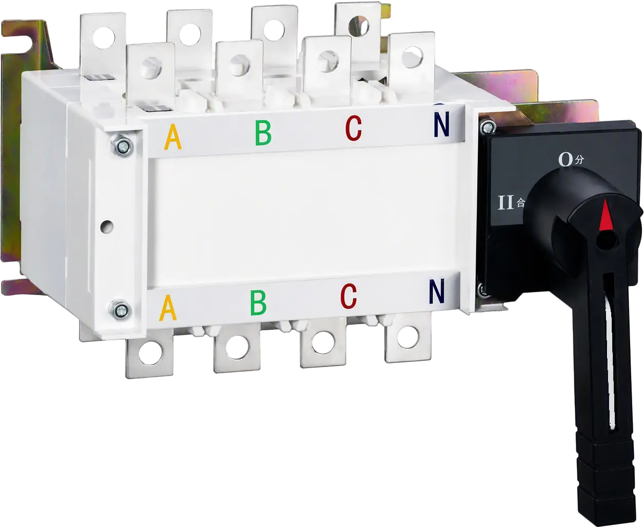
Manual Transfer Switch 125A-3150A 3P/4P AC400V

The EKGLZ1 manual transfer switch lets operators change a low-voltage load between two power sources by hand, isolating both circuits completely. Rated 125A to 3150A at AC400V in 3-pole and 4-pole versions, it prevents parallel supply and reverse power transmission.

Request a Quote

Pricing is quoted per order — tell us your quantity and destination and our sales team will respond with a full offer.

ModelEKGLZ1
AvailabilityIn stock
  • CE & TUV certified
  • Worldwide shipping
  • OEM & ODM support

Product Features of Manual Transfer Switch

The EKGLZ1 series is a manual transfer switch built to IEC/EN 60947-3 for low-voltage power distribution. Each switch isolates the two supply circuits completely, so it works as a manual disconnect switch for both sources and removes the risk of parallel power supply.

  • Standard: IEC/EN 60947-3.
  • Poles: 3P and 4P versions.
  • Rated operated voltage: 400V, 50Hz.
  • Rated current: 125A to 3150A (16 current ranks).
  • Energy-stored quick break design with good arc extinction.
  • FRP housing: flame-retardant, insulated, and impact-resistant.
  • Safe changeover: prevents reverse power transmission and equipment burnout caused by misconnection, giving loads a continuous, safe supply.
  • Configurable: external handle or direct operation; 1NO+1NC or 2NO+2NC auxiliary contacts; front or back board wiring.
Manual Transfer Switch

Commercial Applications of Manual Transfer Switch

As a non automatic transfer switch, the EKGLZ1 puts the changeover decision in the operator’s hands. That suits commercial and industrial sites where a manual transfer switch is preferred for planned, supervised source changes.

Applications & Use Cases

  • Mains / standby changeover: manually shifting a load between the utility supply and a backup source while keeping the two circuits fully isolated.
  • Dual-feeder distribution panels: selecting between two incoming supplies in low-voltage switchboards and control panels.
  • Maintenance isolation: disconnecting a supply for servicing while the other source stays available (positions I / O / II).
  • Panel building and OEM integration: 125A to 3150A frames in 3P or 4P, with front or back board wiring to suit the enclosure layout.

Technical Specifications of Manual Transfer Switch

This manual electrical transfer switch is rated AC400V, 50Hz across the whole series. Ratings change with frame size, as listed per current rank below.

Common parameterValue
StandardIEC/EN 60947-3
Rated working voltage (Ue)AC400V
Rated frequency50Hz
Poles3P, 4P
Rated current range125A – 3150A


Ith / IeUiUimpUsage categoryIcm (kA)IcwMech. life (times)Elec. life (times)Operation moment (N·m)
125A690V8kVAC-22B1710kA/1s14002006.5
160A690V8kVAC-22B1710kA/1s14002006.5
200A800V8kVAC-22B1710kA/1s140020010
225A800V8kVAC-22B1710kA/1s140020015
250A800V8kVAC-22B1710kA/1s140020015
315A800V8kVAC-22B4020kA/1s80020015
400A800V8kVAC-22B4020kA/1s80020015
500A800V8kVAC-22B4020kA/1s80020015
630A800V8kVAC-22B4020kA/1s80020015
800A1000V10kVAC-21B10535kA/1s50010027
1000A1000V10kVAC-21B10535kA/1s50010027
1250A1000V10kVAC-21B10535kA/1s50010027
1600A1000V10kVAC-21B10535kA/1s50010027
2000A1000V10kVAC-21B10535kA/1s30010060
2500A1000V10kVAC-21B10535kA/1s30010060
3150A1000V10kVAC-21B10535kA/1s30010060
  • Ith = conventional heating current;
  • Ie = rated working current (equal to Ith for each rank);
  • Ui = rated insulation voltage;
  • Uimp = rated impulse withstand voltage;
  • Icm = rated short-circuit making capacity;
  • Icw = rated short-time withstand current.

Dimensions and Wiring of Manual Transfer Switch

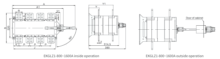
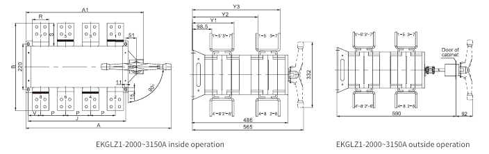
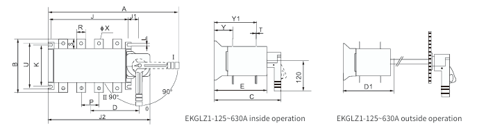
Check the installation dimensions below before ordering a manual transfer switch system. Drawings show inside operation and outside (door-mounted handle) operation; all dimensions are in mm.

EKGLZ1-125~630A

EKGLZ1-125~630A

ModelABCDD1EJJ1J2KLPRSTUØXYY1
EKGLZ1-125A~160A/330213522889190160120371959573620253.5115955.5126.5
EKGLZ1-125A~160A/4332135228105190160150372259573620253.5115955.5127.5
EKGLZ1-200A~250A/33421652501122151801603723511695025283.514010.563145
EKGLZ1-200A~250A/43921652501372181802103728511695025283.514010.563147
EKGLZ1-315A~400A/341023430715027825120646.529817610653237520510.583193
EKGLZ1-315A~400A/446023430718027825126746.535817610653237520510.583193
EKGLZ1-500A~630A/341025030715027825120646.529817610654045621512.583.5193.5
EKGLZ1-500A~630A/446025030718027825126746.535817610654045621512.583.5193.5

EKGLZ1-800~1600A

EKGLZ1-800~1600A

ModelAA1BJPRSTVYY1
EKGLZ1-800~1000A/35884553283561206064856.5109254
EKGLZ1-800~1000A/47025693284701206064860109254
EKGLZ1-1250A/35884553363561208068856.5109254
EKGLZ1-1250A/47025693364701208068860109254
EKGLZ1-1600A/358845533635612080681056.5110255
EKGLZ1-1600A/470256933647012080681060110255

EKGLZ1-2000~3150A

EKGLZ1-2000~3150A

ModelAA1BJPRSTVY1Y1Y2
EKGLZ1-2000A/3588455422356120801111056.5211.5332.5445.5
EKGLZ1-2000A/4702569422470120801111060211.5332.5445.5
EKGLZ1-2500A/3588455432356120801161556.5216.5332.5450.5
EKGLZ1-2500A/4702569432470120801161560216.5332.5450.5
EKGLZ1-3150A/3588455442356120801212056.5221.5332.5455.5
EKGLZ1-3150A/4702569442470120801212060221.5332.5455.5

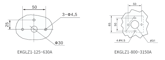
Outside operation handle base installation

Handle base cut-outs differ by frame size: 125–630A uses 3-Φ4.5 mounting holes with a Φ30 opening; 800–3150A uses 4-Ø4.5 mounting holes with a Ø31 opening.

Outside operation handle base installation

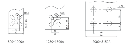
Wiring bus (800~3150A)

Wiring bus (800~3150A)


Request a Quote

Get pricing for EKGLZ1

Complete the form and our sales engineers will reply with pricing, lead time and certification documents.

Chat on WhatsApp