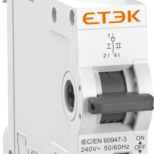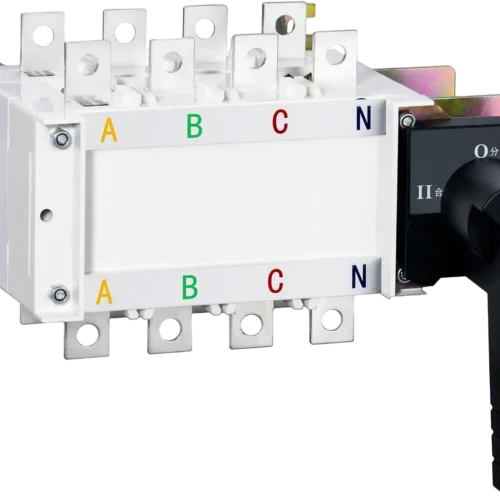
ATS with Controller: PC-Class Automatic Transfer Switch, 16A to 630A

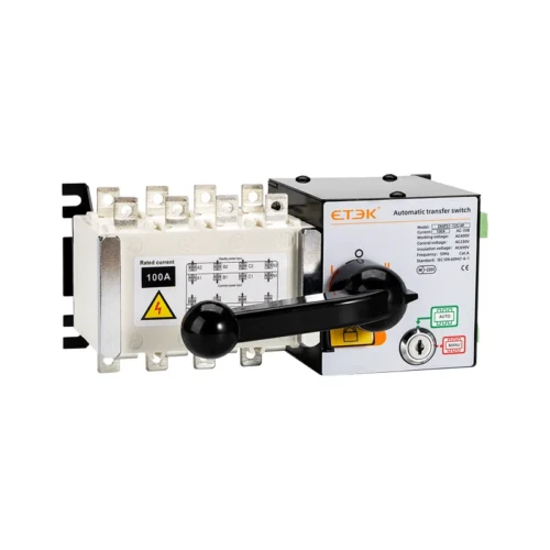
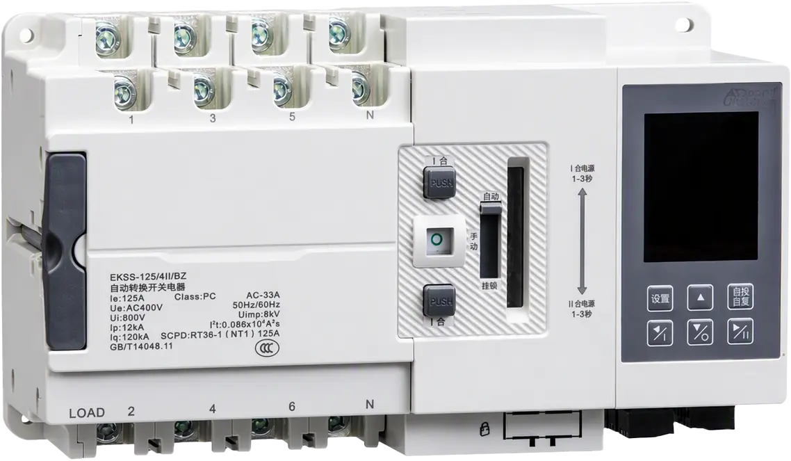
The EKS5 ATS with controller is a PC-class automatic transfer switch for 50/60Hz systems, rated 16A to 630A. It transfers loads between two power sources in 70 to 100ms, supports generator control, and complies with IEC 60947-6-1 for dependable critical power.

Request a Quote

Pricing is quoted per order — tell us your quantity and destination and our sales team will respond with a full offer.

ModelEKS5
AvailabilityIn stock
  • CE & TUV certified
  • Worldwide shipping
  • OEM & ODM support

Product Features of ATS with Controller

This ATS with controller combines a fast PC-class switching mechanism with an intelligent LED/LCD controller:

  • Fast transfer: minimum converting action time of 70ms (125A/250A frames) and 100ms (400A/630A frames).
  • Wide current range: 16A to 630A across four shell frames (125, 250, 400, 630) in 2P, 3P and 4P versions.
  • High breaking capacity: rated limited short-circuit current of 120kA, with circuit breakers or fuses used as SCPD.
  • Utilisation category: AC-33A (AC-33iA for the 630A frame).
  • Two or three contact positions: selectable two-sectional or three-sectional contact type (F-menu setting).
  • Two controller grades: Type A (standard) and Type B (high grade, with split operation, Modbus RS485 remote control and timing start).
  • Operating modes: self-throwing self-resetting, self-throwing non-self-resetting, and mutually backup modes.
  • Full voltage and frequency monitoring: phase-failure, under-voltage, over-voltage and lost-voltage detection on A/B/C for both routes; 40Hz–60Hz adjustable frequency detection.
  • Adjustable settings: under-voltage 161V–196V (default 187V), over-voltage 242V–301V (default 263V), conversion and return delay 0–180s (default 0.5s).
  • Generator control: built-in dry-contact relay (terminals 501–502) for generator start/stop signals.
  • Fire-fighting linkage: programmable input/output on three-sectional products; pulse or continuous signal types.
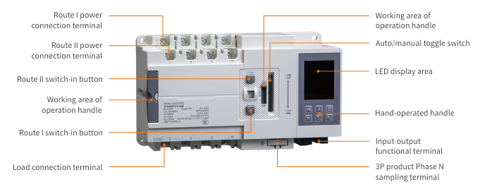
  • Display and installation: integrated LED digital screen or split LCD screen; integrated or split installation; manual handle with Auto/Manual toggle.
ats with controller

Commercial Applications of ATS with Controller

An ATS with controller such as the EKS5 switches between a common (mains) supply and a standby supply, or a generator, whenever one source becomes abnormal. This keeps essential commercial and industrial loads continuously powered, while the controller handles voltage monitoring, delays and generator start signals automatically.

Applications & Use Cases

  • Construction: temporary and permanent site power with generator backup.
  • Industry: production lines and process equipment that cannot tolerate supply interruption.
  • Finance: banking, trading, and data-processing facilities.
  • Medical: hospitals and clinics where life-support and critical systems need uninterrupted power.
  • Communication: telecom exchanges and base stations.
  • Data centers: mains-to-generator or dual-feeder changeover for servers and cooling.
  • Airports: terminals, lighting, and control systems.
  • Rail transit: stations, signalling, and tunnel systems, with fire-fighting linkage.
  • Sports venues: stadium lighting, broadcast, and safety systems.

Technical Specifications of ATS with Controller

The table below lists the main parameters of the EKS5 ATS with controller by shell frame.

Parameter 125 250 400 630
Poles of switch 2P, 3P, 4P 3P, 4P 3P, 4P 3P, 4P
Rated working current 16, 20, 32, 40, 50, 63, 100, 125A 125, 160, 200, 225, 250A 250, 315, 400A 400, 500, 630A
Category of use AC-33A AC-33A AC-33A AC-33iA
Rated working frequency 50/60Hz 50/60Hz 50/60Hz 50/60Hz
Rated working voltage AC220/230V (2P), AC380/400V (3P/4P) same same same
Controlling power supply AC230V AC230V AC230V AC230V
Rated insulation voltage 800V 800V 800V 800V
Rated impulse withstand voltage 8kV 8kV 8kV 8kV
Rated limited short-circuit current 120kA* 120kA* 120kA* 120kA*
SCPD fuse Ip 12kA 27kA 42kA 59kA
SCPD fuse I²t 0.068×10⁶ A²s 0.3×10⁶ A²s 2.0×10⁶ A²s 3.9×10⁶ A²s
Minimum converting action time 70ms 70ms 100ms 100ms
Contact working positions II or III II or III II or III II or III
External dimension (L×W×D) 238×140×115mm 292×190×132mm 375×285×195mm 375×285×195mm

Controller Functions: Type A vs Type B

Function Type A (standard) Type B (high grade)
Rated control power supply AC230V 50/60Hz AC230V 50/60Hz
Auxiliary power supply DC24V DC24V
Operation mode Auto; handle operation Auto; handle; split operation; communication remote control
Conversion way Self-throwing self-resetting; self-throwing non-self-resetting Same
Display LED digital (integrated) / LCD (split) Same
Common / backup monitoring Phase failure, under-, over- and lost-voltage (A, B, C) Same
Generator control Yes (one dry-contact relay set) Yes (one dry-contact relay set)
Fire-fighting linkage Default unavailable; module can be added Default unavailable; module can be added
Frequency detection 40Hz–60Hz adjustable 40Hz–60Hz adjustable
Timing start None Timing conversion
Conversion / return delay 0.5s default, 0–180s adjustable 0.5s default, 0–180s adjustable
Under-voltage setting 161–196V (default 187V, ±3V, 10V hysteresis) Same
Over-voltage setting 242–301V (default 263V, ±3V, 10V hysteresis) Same
Main-power selection Route I priority (b-3 = 0, default); Route II priority (b-3 = 1) Same
Communication None RS485 Modbus (301 A+, 302 B-, 303 GND)
Installation Integrated; split Integrated; split

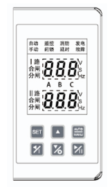
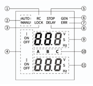
Display Panel and Keypad

Display panel layout
Display panel layout (callouts 1–11)
Controller front panel and keypad
Controller front panel and keypad (SET, ▲, AUTO/MANU)

F-Menu Settings

Press SET, enter password 888 (default), press SET three times to enter the F menu, then use ← / → to browse and ▲ / ▼ to change values. Press AUTO/MANU to save and exit.

Item Options
F-1 programmable input 0: fire-fighting (default); 1: short-circuit block; 2: remote power cut-off
F-2 programmable output 0: fault alarm; 1: power grid alarm; 2: load unloading; 3: fire-fighting feedback (default); 4: both routes output separately
F-3 input edge 0: pulse (default); 1: high level
Both-route abnormal conversion 0: non-action (default); 1: both separate
Number of contact positions 0: three-sectional; 1: two-sectional
System frequency 0: 50Hz; 1: 60Hz

Operating Modes

  • Self-throwing self-resetting (default): transfers to the backup source when the common source fails and returns to the common source once it recovers.
  • Self-throwing non-self-resetting: transfers to the backup source on failure and stays there after the common source recovers; non-action or generator control if the backup fails.
  • Mutually backup: either source can serve as the common supply; the switch transfers when the active source becomes abnormal.


Dimensions and Wiring of ATS with Controller

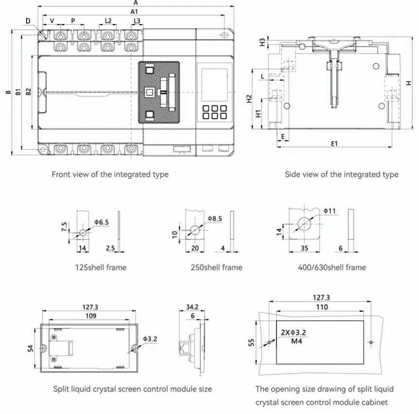
Correct sizing and terminal wiring are essential when installing an ATS with controller. The EKS5 offers 125, 250, 400/630 shell frames; the dimensions below are in mm.

ats with controller

Dimension (mm) 125A 4P 125A 3P 125A 2P 250A 4P 250A 3P 400/630A 4P 400/630A 3P
A (external) 238 213 188 292 188† 375 330
B 140 140 140 190 190 285 285
H 115 115 115 132 132 195 195
B2 (external) 75 75 75 109 109 140 140
H3 5 5 5 6 6 12 12
A1 (mounting) 220 195 170 270 235 345 300
B2 (mounting) 115 115 115 170 170 252 252
H1 34 34 34 44 44 56 56
H2 68.5 68.5 68.5 86 86 106 106
E1 124 124 124 165 165 250 250
E 15.5 15.5 15.5 17 17 27 27
D 4.5 4.5 4.5 6.5 6.5 11 11
V 20.5 20.5 20.5 26.5 26.5 40 40
P 25 25 25 35 35 45 45
L 17.5 17.5 17.5 20 20 33 33
L2 18 18 18 36 36 37 37
L3 12.5 12.5 12.5 17.5 17.5 21.5 21.5

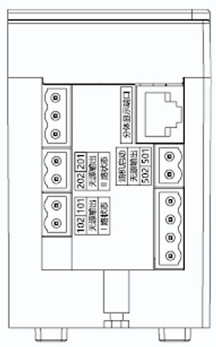
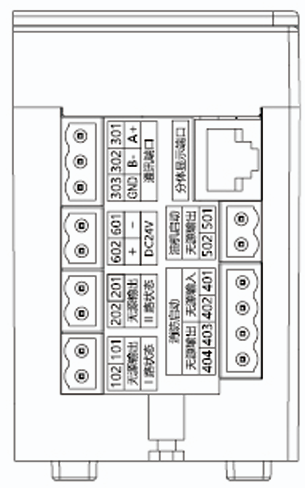
Controller Terminal Definitions

Terminals Function
101–102 Passive signal output: Route I switched-in indicator (contact 5A/250VAC)
201–202 Passive signal output: Route II switched-in indicator (contact 5A/250VAC)
301–303 RS485 Modbus (A+, B-, GND): remote control, switch status and fault code reading
401–402 Programmable passive closed input: fire linkage (default) or prohibition of remote-control conversion
403–404 Programmable passive closed output: fault alarm, power grid alarm, load unloading, fire feedback (default), separate output of Route I/II (0.6A/250VAC, 1.0A/30VDC)
501–502 Generator start/stop dry contact (default); Route II abnormal output when separate-output function is on (0.6A/250VAC, 1.0A/30VDC)
601–602 DC24V auxiliary power input, needed for delayed generator start or remote monitoring when both routes are powerless
Controller terminal layout – Type A
Controller terminal layout – Type B

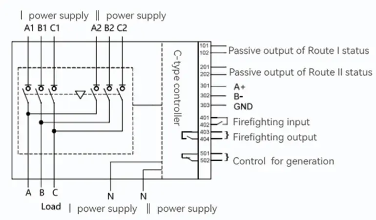
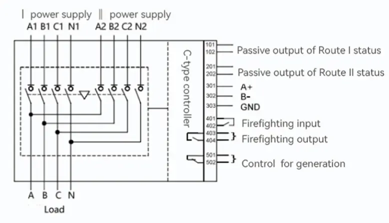
Wiring Diagram (3P and 4P)

  • Both power supplies connect to the Route I (A1 B1 C1 [N1]) and Route II (A2 B2 C2 [N2]) terminals, with the common load output at A B C [N].
  • Terminals 101–102 and 201–202 give Route I/II status, 301–303 give RS485 A+/B-/GND communication, 401–404 handle fire-fighting input/output and 501–502 provide generator control.
  • The secondary wiring of the Type A controller is the same as Type B, only without some Type B functional terminals.
3P wiring diagram
3P wiring diagram
4P wiring diagram
4P wiring diagram


Request a Quote

Get pricing for EKS5

Complete the form and our sales engineers will reply with pricing, lead time and certification documents.

Chat on WhatsApp