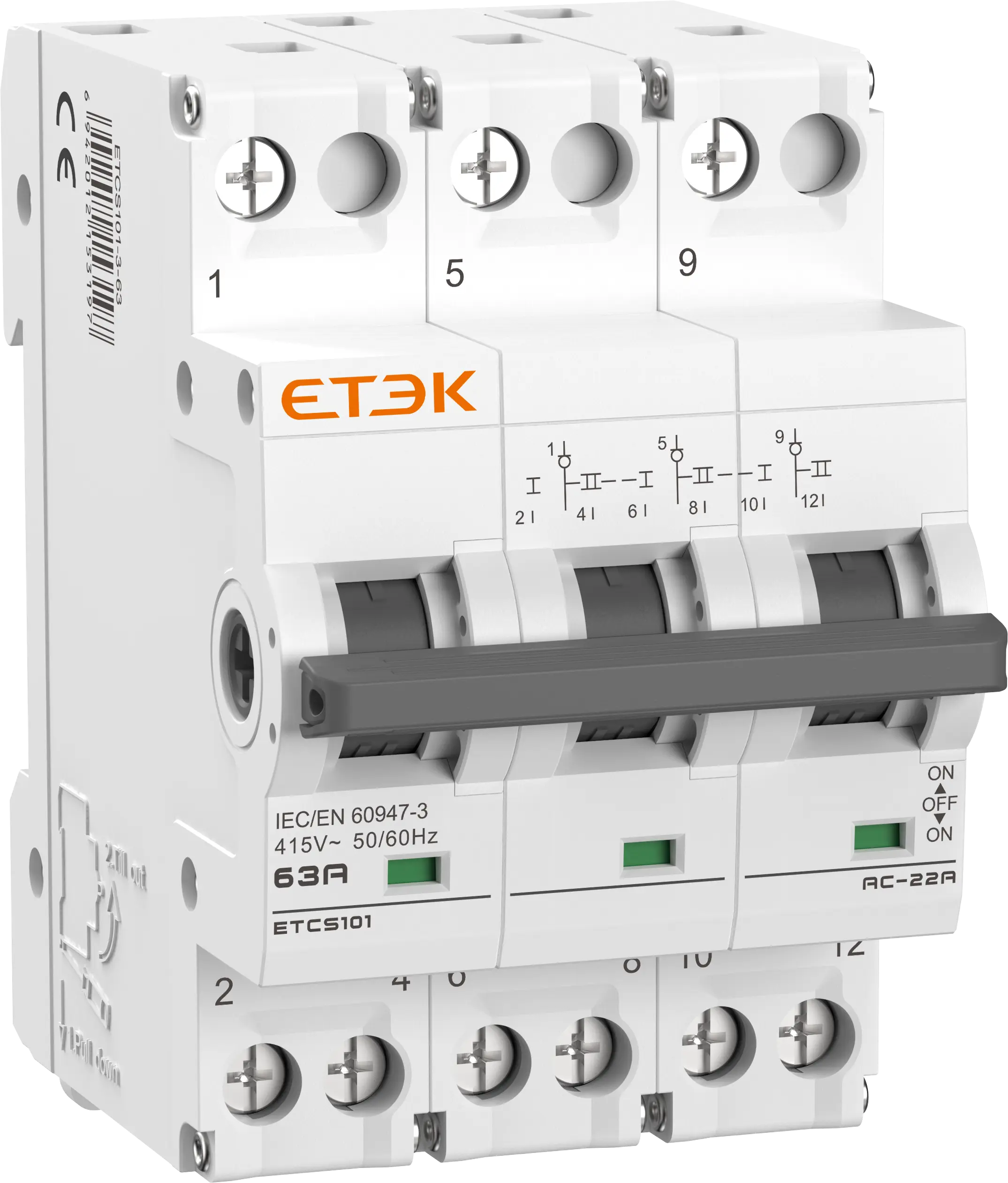
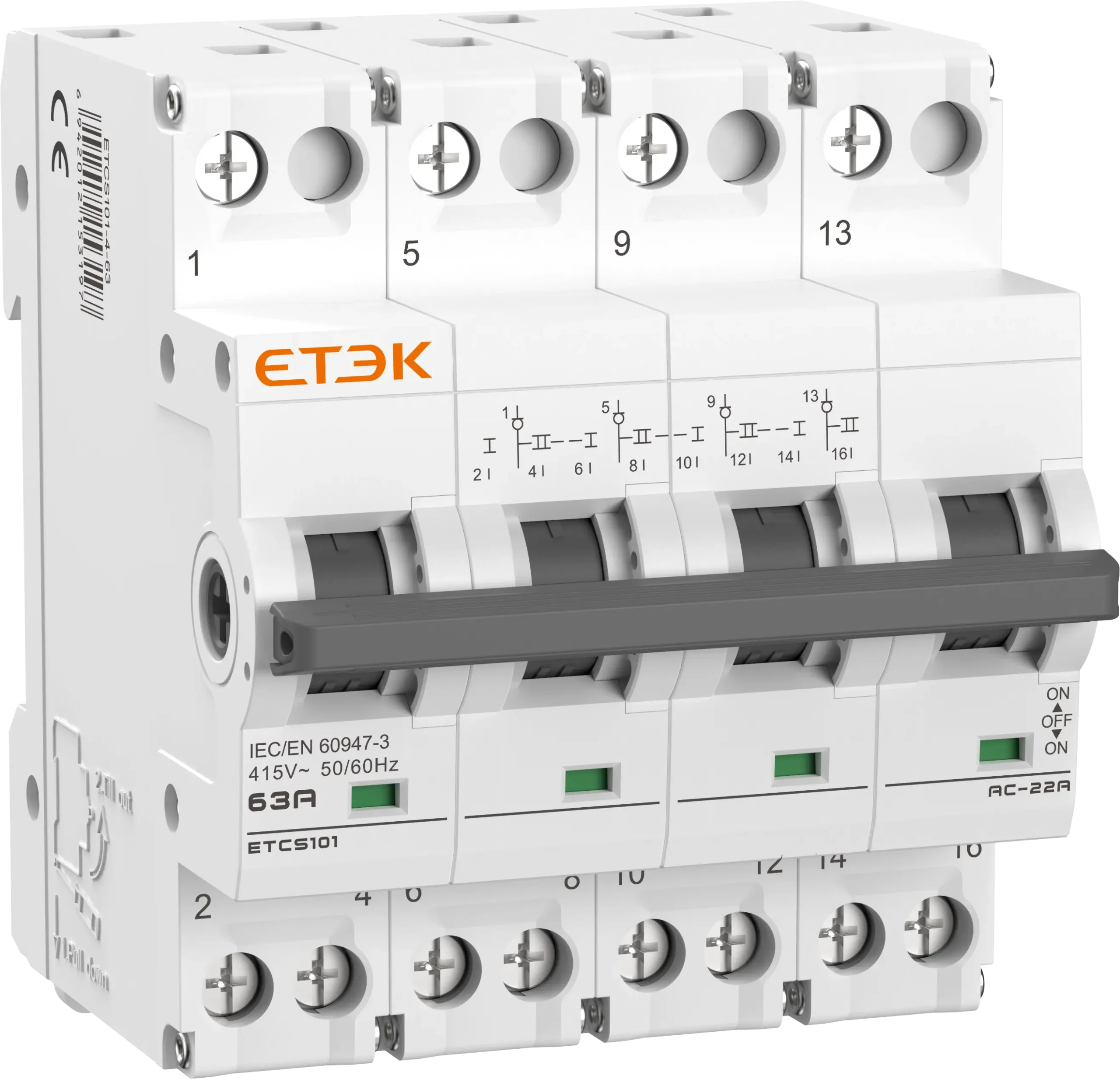
Modular Changeover Switch – 63A (I–O–II)

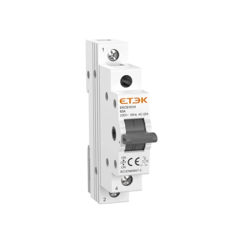
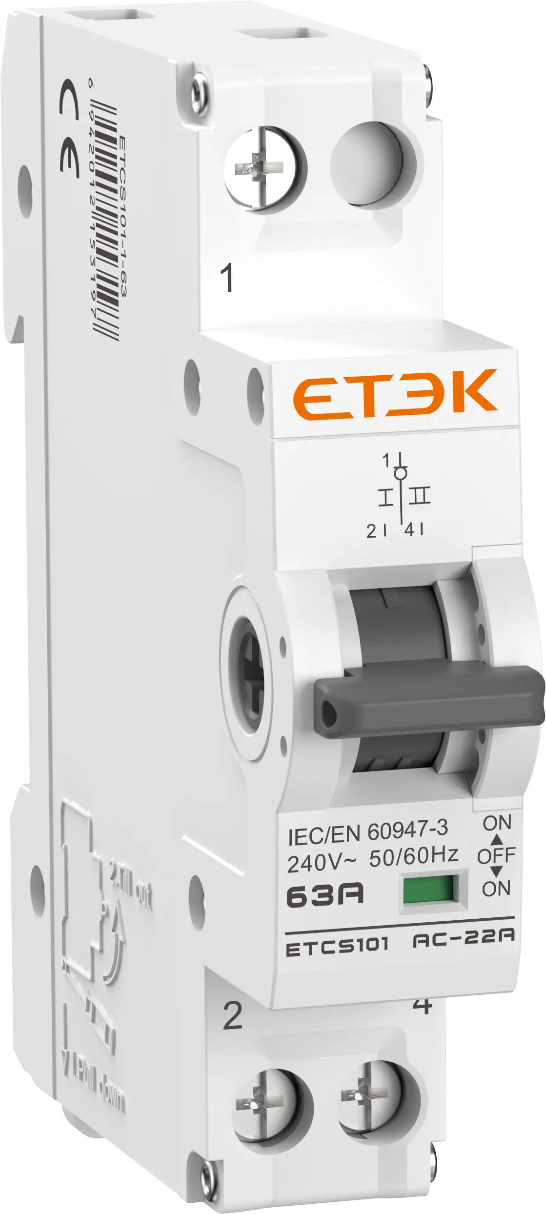
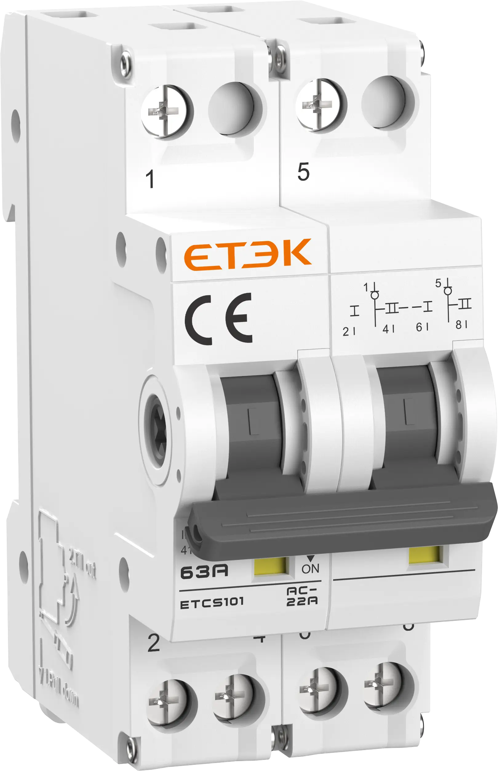
The ETCS101 modular changeover switch is a DIN-rail manual transfer switch for changing over between two power sources. Rated 63A, 230/400V, 50/60Hz, it offers three stable I–O–II positions, clear colour indication and 1P to 4P configurations.

Request a Quote

Pricing is quoted per order — tell us your quantity and destination and our sales team will respond with a full offer.

ModelETCS101
AvailabilityIn stock
  • CE & TUV certified
  • Worldwide shipping
  • OEM & ODM support

Product Features of Modular Changeover Switch

The ETCS101 modular changeover switch combines compact DIN-rail design with dependable manual changeover performance:

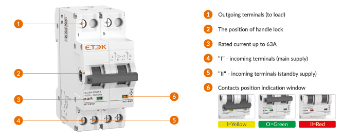
  • Three stable positions (I–O–II): position O is the OFF state, so the load is fully isolated between the main and standby supply.
  • Load-break function: as a switch disconnector, it is suitable for making, carrying (load switching), and breaking the circuit under normal conditions.
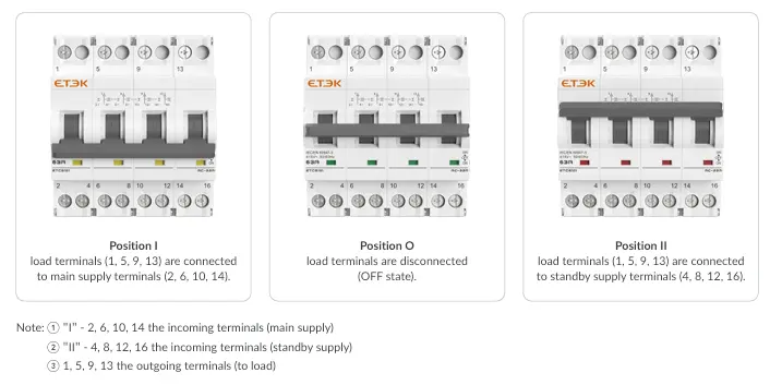
  • Three-colour position indication: a window shows Yellow for I, Green for O (OFF) and Red for II for instant status recognition.
  • 1P / 2P / 3P / 4P configurations: one range covers single-phase and three-phase changeover needs.
  • Rated current up to 63A: available in 16, 25, 32, 40 and 63A (flexible cable max. 40A / rigid conductor max. 63A).
  • Handle lock: a dedicated handle lock position is provided on the front of the switch.
  • Modular DIN-rail mounting: mounts on a standard 35mm DIN rail inside switchgear assemblies and distribution panels.
  • Standards-based design: complies with IEC/EN 60947-3, carries the CE mark and provides IP20 protection with a 4kV rated impulse withstand voltage.
ETCS101 product tips

Commercial Applications of Modular Changeover Switch

In commercial and light-industrial power systems, the ETCS101 modular changeover switch gives operators a simple, visible way to choose between two supply sources. As an industrial changeover switch, it fits control and distribution systems where three clearly indicated positions allow safe manual transfer between two power supply sources.

Applications & Use Cases

  • Main/Alternate supply path selection in distribution panels and control circuits
  • Night/Off/Day switching of heating or hot water heater loads
  • Auto/Off/Manual switching for machines
  • Forward/Stop/Reverse selection for motor applications
  • Controlled distribution of power paths to an auxiliary/stand-by source

Technical Specifications of Modular Changeover Switch

The table below lists the rated data of the ETCS101 modular changeover switch. As a modular transfer switch built to IEC/EN 60947-3, it is suited to AC 50/60Hz systems up to 415V.

ParameterValue
StandardIEC/EN 60947-3
No. of poles1P, 2P, 3P, 4P
Rated insulation voltage (Ui)500V
Rated operational voltage (Ue)240/415V
Rated frequency50/60Hz
Rated current (Ie)16, 25, 32, 40, 63A
(flexible cable max. 40A / rigid conductor max. 63A)
Rated impulse withstand voltage (Uimp) (1.2/50μs)4kV
Rated short-time withstand current (Icw)480A/1s
Rated short-time making capacity (Icm)800A
Utilization categoryAC-22A
Maximum back-up fuse125A gG
Degree of protectionIP20
Electrical life1500 cycles
Mechanical life8500 cycles
Contact form (switch position)I–O–II (three stable positions);
switching position colours: I = Yellow, O = Green, II = Red
Max. terminal capacityMax. 12mm² (direct);
Max. 16mm² (with crimp terminal lug)
Max. tightening torque2.5Nm
InstallationMounting on 35mm DIN rail
Ambient temperature-5°C ~ +40°C
Pollution degree2

Dimensions and Wiring of Modular Changeover Switch

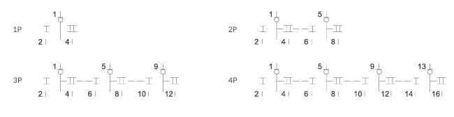
Correct wiring is simple on the ETCS101 modular changeover switch: the main supply connects to the lower terminals of position I, the standby supply to those of position II, and the load to the top terminals. Wiring is shown for every pole configuration, with terminals numbered 1 to 16.

Wiring Diagram

ETCS101 wiring diagram

  • Terminals 2, 6, 10, 14 – “I”: incoming terminals (main supply).
  • Terminals 4, 8, 12, 16 – “II”: incoming terminals (standby supply).
  • Terminals 1, 5, 9, 13: outgoing terminals (to load).

Switch Positions

Dimensions (mm)

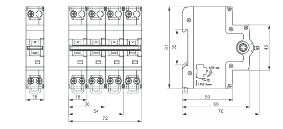
The housing is 18mm wide per pole (18 / 36 / 54 / 72mm for 1P / 2P / 3P / 4P), 81mm high and 76mm deep, with a 35mm DIN rail slot. For compact panel layouts, this manual power switch occupies the same width as standard modular devices.

ETCS101 dimension drawing

Width per pole18mm (1P = 18, 2P = 36, 3P = 54, 4P = 72)
Height81mm
Depth76mm overall
DIN rail slot35mm
Request a Quote

Get pricing for ETCS101

Complete the form and our sales engineers will reply with pricing, lead time and certification documents.

Chat on WhatsApp