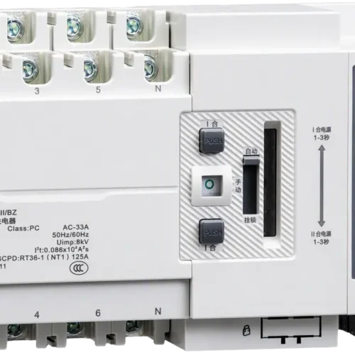
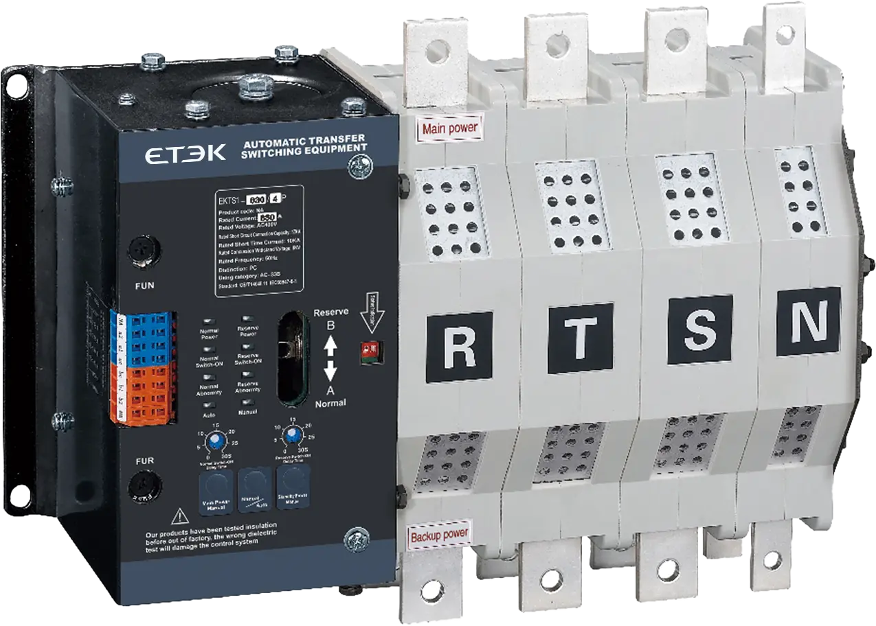
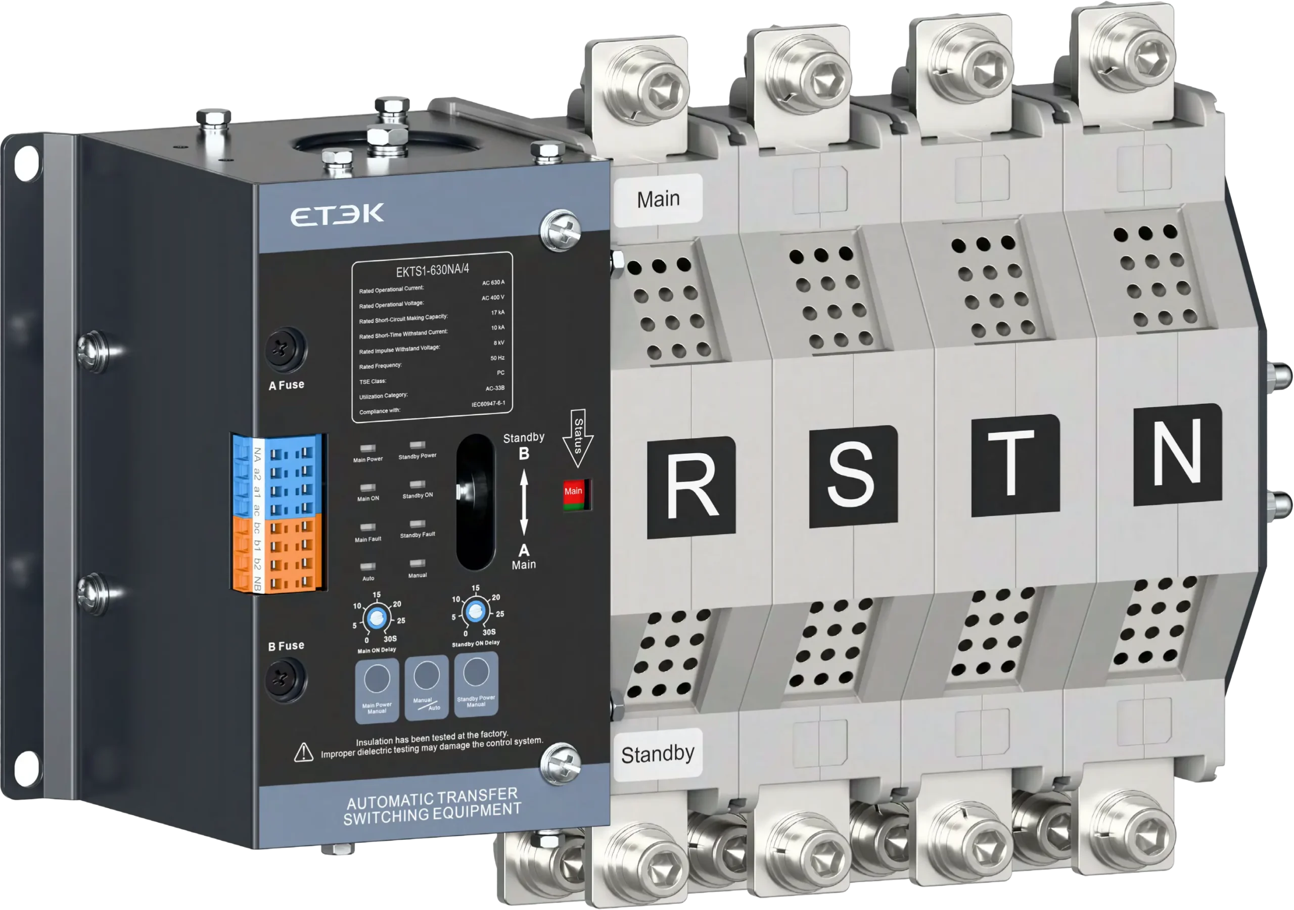
Automatic Changeover Switch ATS, 16A to 630A

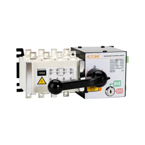
The EKTS1 automatic changeover switch ATS is a PC-class transfer solution that moves critical loads between grid, generator, or battery sources within 900 ms. Rated 16 A to 630 A and compliant with IEC 60947-6-1, it keeps fire safety, telecom, and healthcare systems running.

Request a Quote

Pricing is quoted per order — tell us your quantity and destination and our sales team will respond with a full offer.

ModelEKTS1
AvailabilityIn stock
  • CE & TUV certified
  • Worldwide shipping
  • OEM & ODM support

Product Features of the Automatic Changeover Switch ATS

The EKTS1 automatic changeover switch ATS ensures reliable power for critical applications. It combines an excitation mechanism, microcomputer control, intelligent monitoring, and strong EMC performance, and it operates at 220 V without additional control power.

  • PC-class change-over switch: built to IEC 60947-6-1:2021 for dependable source transfer.
  • Dual power supply design: power supply A (main) and power supply B (standby), covering utility grid, generator, or battery sources.
  • Wide current range: supports AC systems with a rated current of 16 A to 630 A in 32, 125, 250, 400, and 630 A frames.
  • Automatic and manual transfer: suited to three-phase systems, with 2P, 3P, and 4P pole options.
  • Electromagnetic drive: dual-coil DC pulse operation, with the controller powered directly from the 220 V AC line voltage of the main and standby supplies.
  • Fast, controlled transfer: automatic switching time A to B of 900 ms or less, load disconnect time of 100 ms or less, and adjustable return transfer delay (B to A) of 0 to 30 s.
  • Voltage protection: undervoltage value 165 V and overvoltage value 270 V.
  • Generator start control: one normally open output (3 A / AC 230 V) with immediate start and a 5 s stop delay.
  • Isolation indication: switch body with electrical and mechanical lock closing instructions used as the isolation indicators.

Product Models

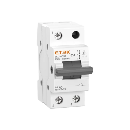
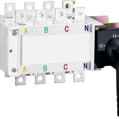
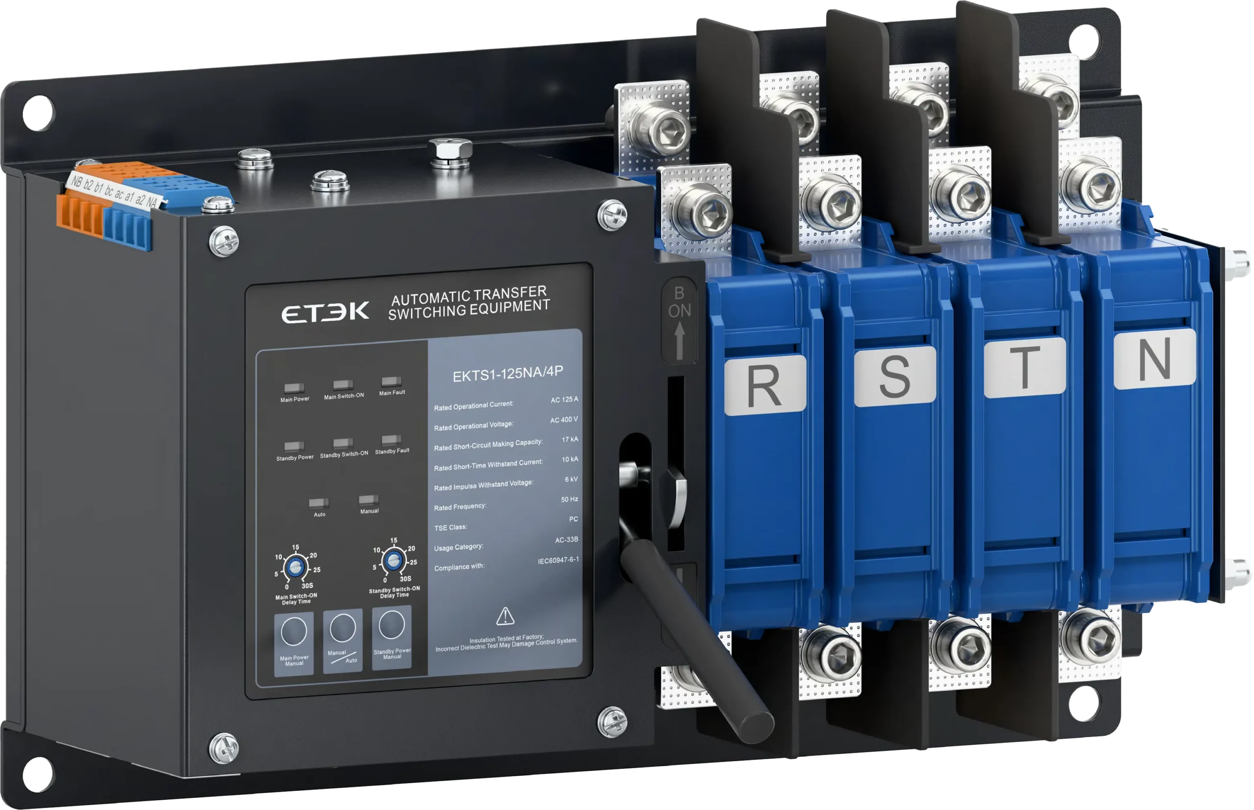
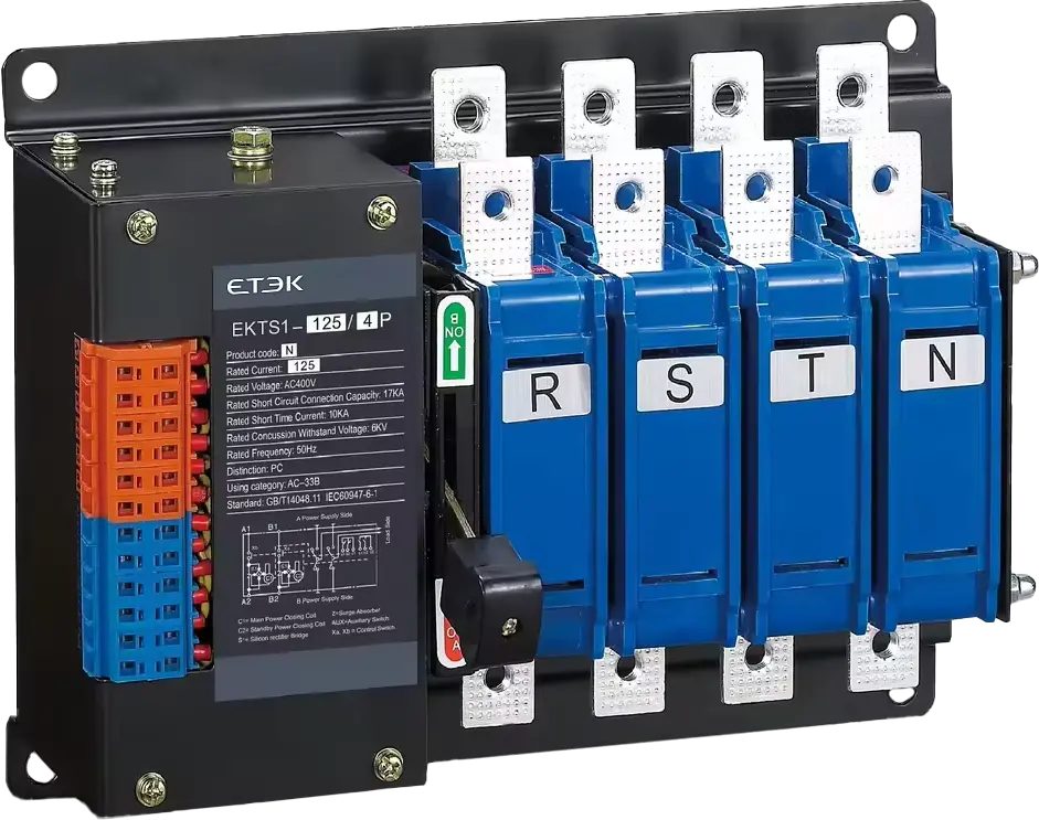
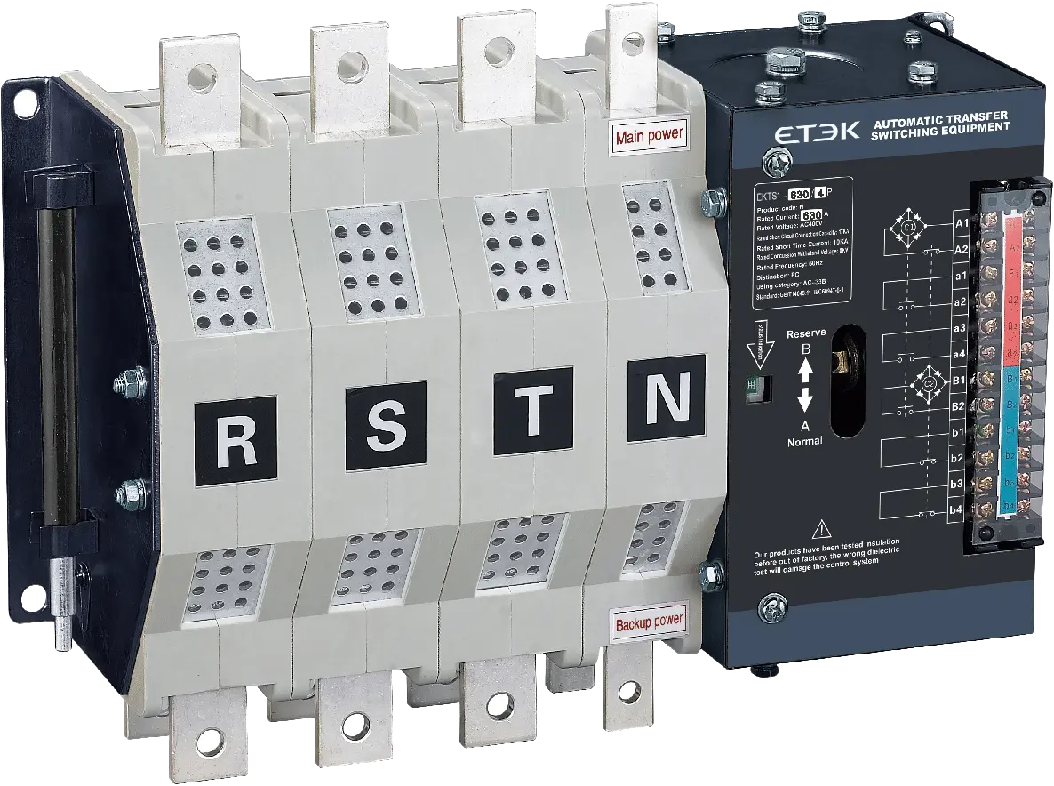
The EKTS1 automatic changeover switch ATS is available as an integral type (NA) and a split type (N), each in 125 A and 630 A frames shown below.
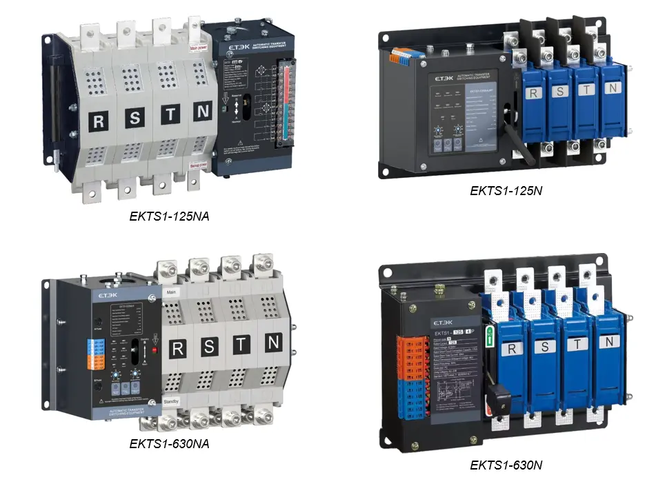
EKTS1 models

Type Designation Guide

Example model code: EK TS1-125 4P NA / 125A R.

PositionCodeMeaning
1EKCompany code
2TS1TS1 series PC-class automatic transfer switch
332, 125, 250, 400, 630Frame grade
42P, 3P, 4PNumber of poles (2P limited to products below 125 A)
5NA / NNA: integral type, 2 positions. N: split type, 2 positions
616, 20, 25, 32, 40, 50, 63, 80, 100, 125, 160, 180, 200, 250, 315, 400, 500, 630 ARated working current
7R / S / FR: self-injection and self-recovery (default). S: self-injection and non-self-recovery. F: grid to generator

Product Structure

The ATSE consists of two major components: the switch body and the controller. The switch body uses an electromagnetic drive with dual-coil DC pulse operation, and the controller draws its working power from the 220 V AC line voltage of the main and standby power supplies, so no separate control power supply is needed.
Commercial Applications of the Automatic Changeover Switch ATS

Wherever a power interruption is not acceptable, the EKTS1 automatic changeover switch ATS keeps essential circuits energized by moving the load to a standby source and returning it to the main source once supply is restored.

Applications & Use Cases

  • Fire protection systems: keeps emergency lighting, pumps, and alarm circuits powered when the utility grid fails.
  • Telecom facilities: transfers base stations and equipment rooms between grid, generator, and battery backup.
  • Healthcare buildings: maintain supply to critical medical loads through fast source switching.
  • Generator backup installations: the grid-to-generator version provides a start-the-engine output for automatic generator start.
  • Grid-to-grid dual feeds: switches between two utility sources for sites with redundant incoming supplies.

Technical Specifications of the Automatic Changeover Switch ATS

The table below lists the rated data of the EKTS1 automatic changeover switch ATS. Check these parameters against your system calculations before specifying a frame size.

ParameterValue
StandardIEC 60947-6-1:2021
TSE classPC-class
Usage categoryAC-33B
Shell frame current32, 125, 250, 400, 630 A
Rated current16, 20, 25, 32 A (32 frame); 40, 50, 63, 80, 100, 125 A (125 frame); 160, 180, 200, 250 A (250 frame); 250, 315, 400 A (400 frame); 500, 600 A (630 frame)
Rated voltage (phase-to-neutral, AC)230 V
Rated operational voltage (phase-to-phase, AC) Ue400 V
Rated insulation voltage Ui690 V
Rated impulse withstand voltage UimpMain circuit 8 kV; control circuit 4 kV
Rated short-time withstand current Icw10 kA (10 kA/60 ms and 10 kA/1 s listed for the larger frames)
Rated short-circuit making capacity Icm17 kA
Rated frequency50 Hz
Number of poles2P, 3P, 4P (2P limited to products below 125 A); 3P, 4P for larger frames
Control circuit155–300 VAC, 50 Hz
Auxiliary circuit70%–120% Ue, 50 Hz; Ie = 6 A (smaller frames) / 10 A (larger frames)
Overvoltage / undervoltage protectionUndervoltage value 165 V / overvoltage value 270 V
Automatic switching time (A to B)900 ms or less
Load disconnect time100 ms or less
Return transfer delay (B to A)Adjustable from 0 to 30 s
Generator start controlOne normally open output (3 A / AC 230 V), immediate start, 5 s stop delay
Operating cycleOne operation per 10 s
Mechanical life20,000 operations (smaller frames) / 17,000 operations (larger frames)
Electrical life6,000 operations


Dimensions and Wiring of the Automatic Changeover Switch ATS

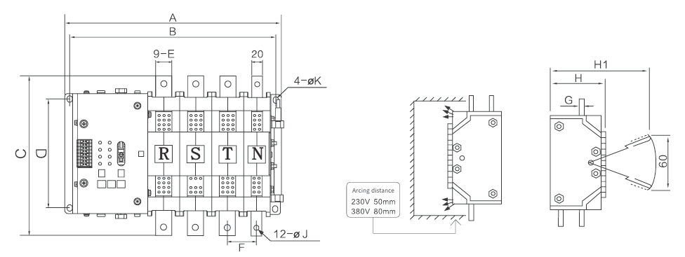
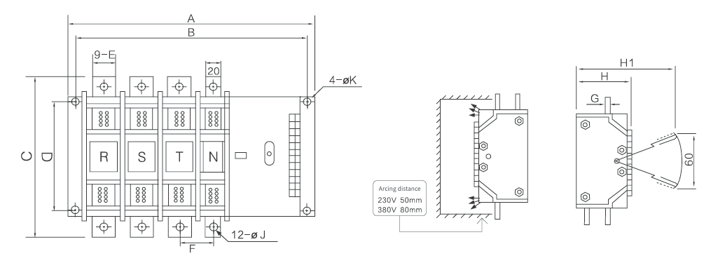
Use the wiring diagrams and dimension drawings below to plan panel space, incoming and outgoing cabling, and mounting for the EKTS1 automatic changeover switch ATS. All dimensions are in millimetres. Keep the arcing distance clear: 50 mm at 230 V and 80 mm at 380 V.

Installation Wiring Diagram

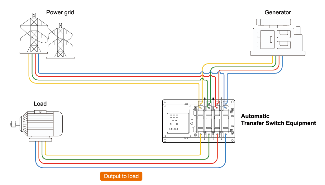
The power grid and the generator feed the automatic transfer switch equipment, which delivers the selected source as output to the load.

EKTS1-installation-wiring-diagram

Terminal Diagram – EKTS1-NA

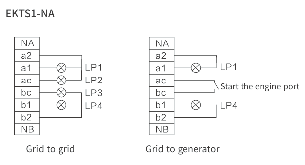
Grid-to-grid and grid-to-generator terminal arrangements for the integral type.

EKTS1-NA terminal diagram
EKTS1-NA terminal diagram: grid to grid and grid to generator
  • NA: 3-pole dedicated main power supply to zero terminal.
  • NB: 3-pole dedicated backup power supply to zero terminal.
  • LP1: main power closing indicator.
  • LP2: main power indicator.
  • LP3: backup power indicator.
  • LP4: backup power close indicator.

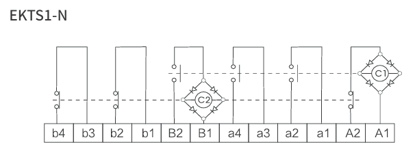
Terminal Diagram – EKTS1-N

EKTS1-N terminal diagram

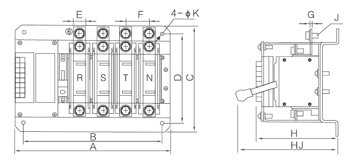
Dimensions – EKTS1-32NA / 125NA (integral type)

EKTS1-32NA 125NA


ModelA 2PA 3PA 4PB 2PB 3PB 4PCDEF 3PF 4PGHJK
EKTS1-32NA216243270196223250184167122727311059
EKTS1-125NA237274311217254291184167203737311089

Dimensions – EKTS1-250NA to 630NA (integral type)

EKTS1-250NA to 630NA


ModelA 3PA 4PB 3PB 4PCDEF 3PF 4PGHH1JK
EKTS1-250NA3223723023522942002049495146295810
EKTS1-400NA35240233238229420030595461462951010
EKTS1-630NA35241233239229420035595961462951210

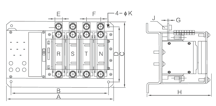
Dimensions – EKTS1-32N / 125N (split type)

EKTS1-32N-125N


ModelA 2PA 3PA 4PB 2PB 3PB 4PCDEFGHHJJK
EKTS1-32N1701972241501772041841671227311015559
EKTS1-125N1912282651912082451841672037311015589

Dimensions – EKTS1-250N to 630N (split type)

EKTS1-250N to 630N


ModelA 3PA 4PB 3PB 4PCDEF 3PF 4PGHH1JK
EKTS1-250N3223723023522942002049495146295810
EKTS1-400N35240233238229420030595461462951010
EKTS1-630N35241233239229420035595961462951210
Request a Quote

Get pricing for EKTS1

Complete the form and our sales engineers will reply with pricing, lead time and certification documents.

Chat on WhatsApp