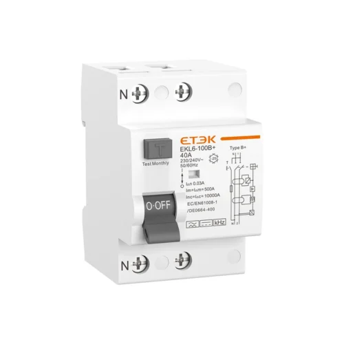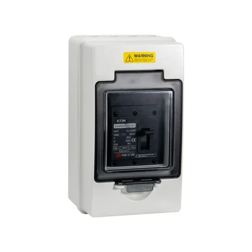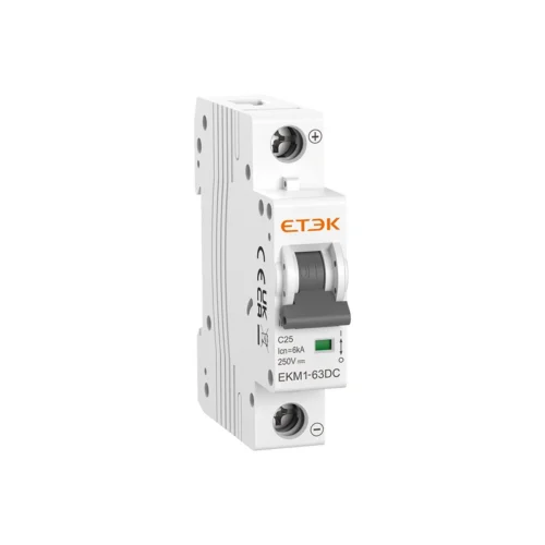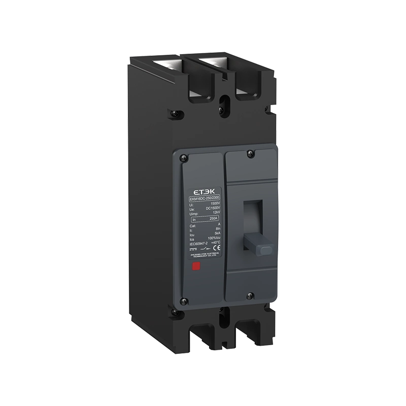
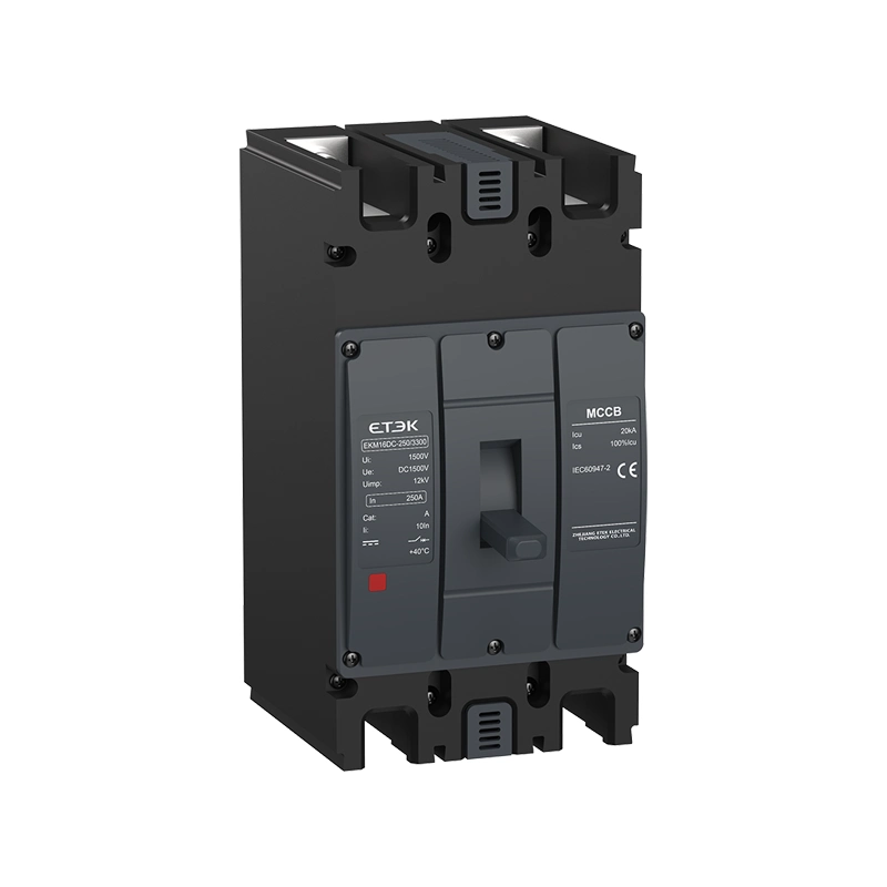
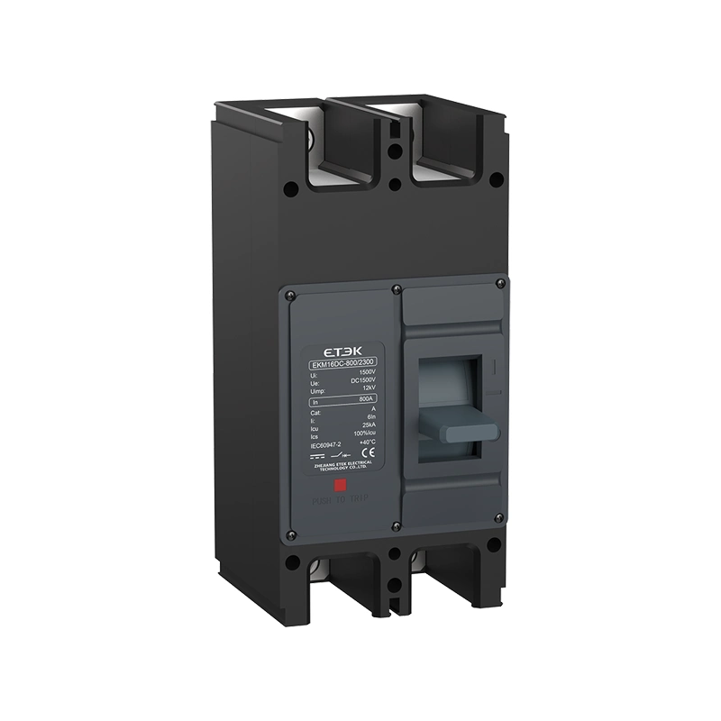
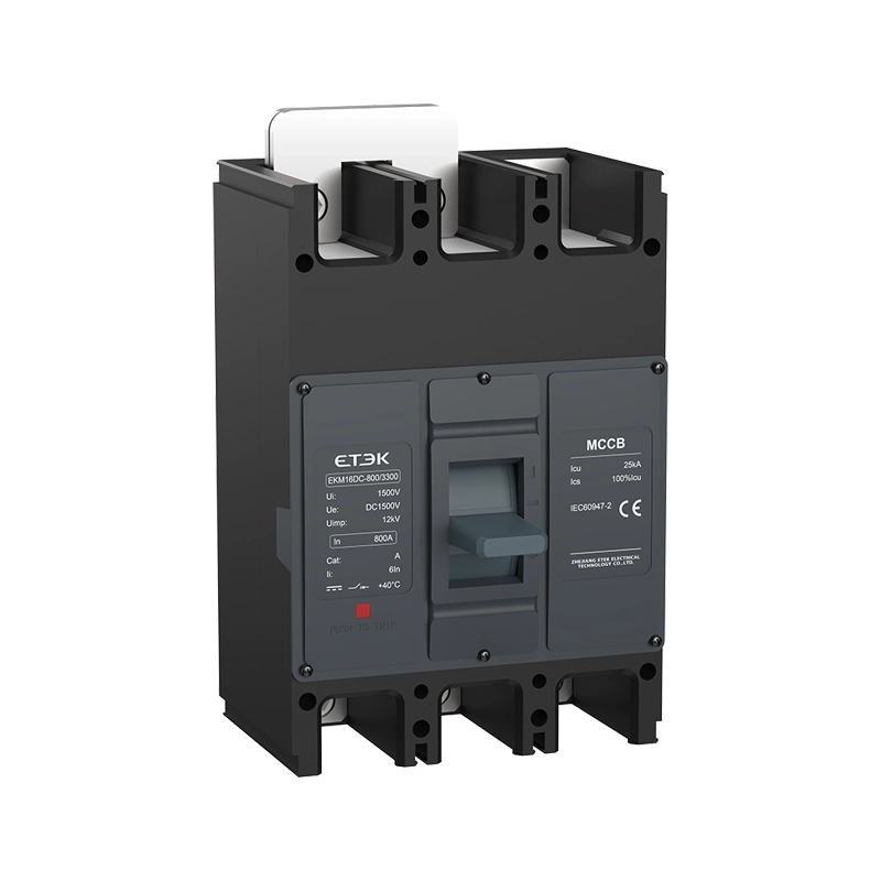
Molded Case Circuit Breaker 1500V DC 800A 50kA MCCB

Engineered for highly demanding new energy applications, this Molded Case Circuit Breaker delivers uncompromising direct current isolation up to 1500V DC. The EKM16DC series functions as an exceptionally robust molded breaker, effortlessly managing massive continuous loads up to 800A to strictly secure commercial photovoltaic arrays and utility-scale wind power systems against devastating short circuits and overloads.

Request a Quote

Pricing is quoted per order — tell us your quantity and destination and our sales team will respond with a full offer.

ModelEKM16DC_MCCB
AvailabilityIn stock
  • CE & TUV certified
  • Worldwide shipping
  • OEM & ODM support

Product Features of the Molded Case Circuit Breaker

Constructed for rigorous electrical environments, this Molded Case Circuit Breaker utilizes an instantaneous electromagnetic release alongside a highly responsive thermal release mechanism.

  • Extreme High-Voltage Capacity: Operates flawlessly at elevated voltages up to 1500VDC, decisively isolating severe faults with a maximum 50kA ultimate short-circuit breaking capacity (Icu).
  • Zero Arc Technology: Engineered with a specialized arcing distance of ≤50mm (and ≤100mm for specific high-voltage variants) to safely extinguish high-voltage DC arcs.
  • Extended Mechanical Lifecycle: Built for massive commercial switching operations, delivering an exceptional mechanical life of up to 20,000 cycles without degradation.
  • Advanced Isolation Function: Fully integrates reliable circuit isolation capabilities, distinctly marked on the faceplate for instant engineering verification.
  • Flexible Environmental Tolerance: Operates reliably in ambient temperatures ranging from -45°C to +70°C and at extreme elevations up to 2000m without derating.
Commercial Applications for the Molded Case Circuit Breaker

Deploying the EKM16DC secures vital high-capacity DC nodes, acting as a highly dependable molded breaker for utility-scale electrical infrastructures.

Applications & Use Cases

  • Utility-Scale Solar Arrays: Functions as the primary molded breaker within central combiner boxes, safely aggregating and isolating the output loading of massive 1500VDC strings.
  • Wind Power Systems: Secures the internal loading capacity of complex wind turbine generator networks against severe electrical overloads and short circuits.
  • Industrial Heavy Machinery: Protects specialized manufacturing equipment operating on massive direct currents, ensuring flawless zero-interruption fault isolation.

Technical Specifications with the Molded Case Circuit Breaker

Evaluate the exact voltage ratings and massive breaking capacities below to seamlessly integrate this Molded Case Circuit Breaker into your heavy-duty DC distribution panels.

General & Electrical Data (IEC 60947-2)

Model EKM16DC-250 / 315 EKM16DC-400 / 400V EKM16DC-630 / 630V EKM16DC-800
2P 3P 2P 3P 2P 3P 2P 3P
Rated frame current Inm (A) 250, 315 400 630 800
Rated current In (A) 63 – 315 250 – 400 400 – 630 630 – 800
Rated operational voltage Ue (V) DC250V, DC500V, DC750V, DC1000V, DC1250V (2P only), DC1500V
Rated insulation voltage Ui (V) 1500
Rated impulse withstand Uimp (kV) 12
Rated ultimate short-circuit breaking capacity Icu (kA)
DC250V / DC500V (2P & 3P) – – 25 70 25 70 25 25
DC750V (2P & 3P) – – 15 50 15 50 15 15
DC1000V (2P) 15 – 15 – 15 – 15 –
DC1000V (3P) – – – 30 – 30 – 30
DC1250V (2P only) – – – 20 – 20 – –
DC1500V (2P & 3P) 5 20 10 25 10 25 10 25
Rated service capacity Ics (kA) 100% Icu
Mechanical life (Times) 20,000 15,000 20,000 15,000
Electrical life (Times) 1500 1000 800 1500 (2P), 800 (3P)
Arcing distance (mm) ≤50 ≤100

Quick Selection Table

Utilize the configuration codes below to precisely specify the EKM16DC series molded case circuit breaker for your exact commercial power needs.

EKM16DC 630 V Z 3 300 630
↓ ↓ ↓ ↓ ↓ ↓ ↓ ↓
Product code Frame current High breaking Operation mode Poles Accessory code Rated current (A) Installation method
EKM16DC
Series
DC MCCB
250, 315, 400,
630, 800
None: No
V: High breaking
None: Direct operation
P: Electrically operation
Z: Turning handle
2P, 3P See accessory
table
63,80,100,125,
140,160,180,200,
225,250,280,300,
315,400,500,630,
700,800
Front connection
(optional)

Selection of Cross-sectional Areas of Connecting Busbars and Cables

Ensure optimal power transmission and prevent thermal degradation by utilizing the correct copper busbar or cable cross-sections.

Selection of Busbars
Rated current (A) 63 80 100 125 160 180-225 250 280-300 315-400
Cross-sectional area (mm²) 16 25 35 50 70 95 120 185 185 (280-300A), 240 (315-400A)
Selection of Cable
Rated current (A) Cross-sectional areas of cables Copper busbar size
Quantity Sectional area (mm²) Quantity Sectional area (mm)
500 2 150 2 30 × 5
630 2 185 2 30 × 8
700 2 240 2 50 × 5
800 2 240 2 50 × 5

Product Protection Requirements for Power Distribution

Rated current (A) Thermal release (ambient temperature +40°C) Tripping current of electromagnetic release
Non-operation time at 1.05 times rated current (cold state) in hours Operation time at 1.3 times rated current (hot state) in hours
63 ≥1 ≤1 10 In ± 20%
63 < In ≤ 800 ≥2 ≤2

Power Loss Table

Model Current when energized (A) Total Power Loss for Three-phase/Four-phase (W)
EKM16DC-250 250 40
EKM16DC-315 315 43
EKM16DC-400 400 115
EKM16DC-400V 400 105
EKM16DC-630 630 187
EKM16DC-630V 630 127
EKM16DC-800 800 262

Applicable Working Environment and Compensation Coefficient

Model Ambient Temperature
+40°C +45°C +50°C +55°C +60°C +65°C +70°C
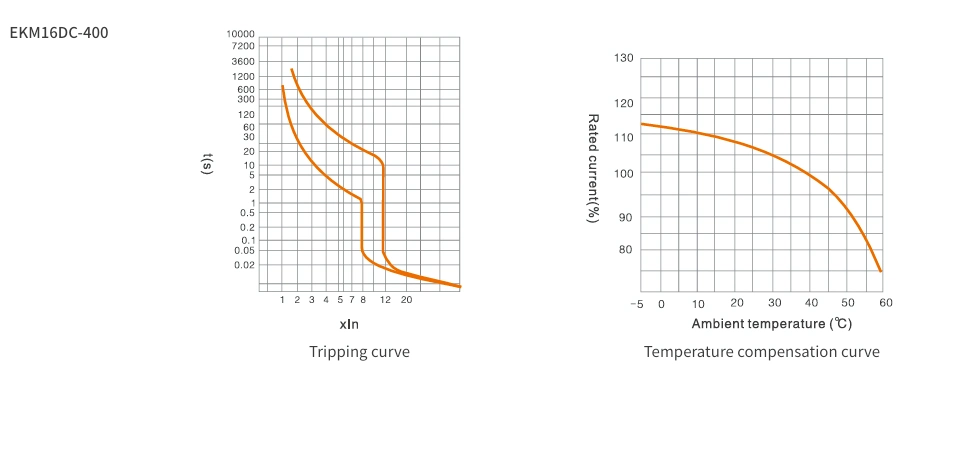
EKM16DC-250 / 315 / 400 1.0In 1.0In 1.0In 0.95In 0.93In 0.91In 0.88In
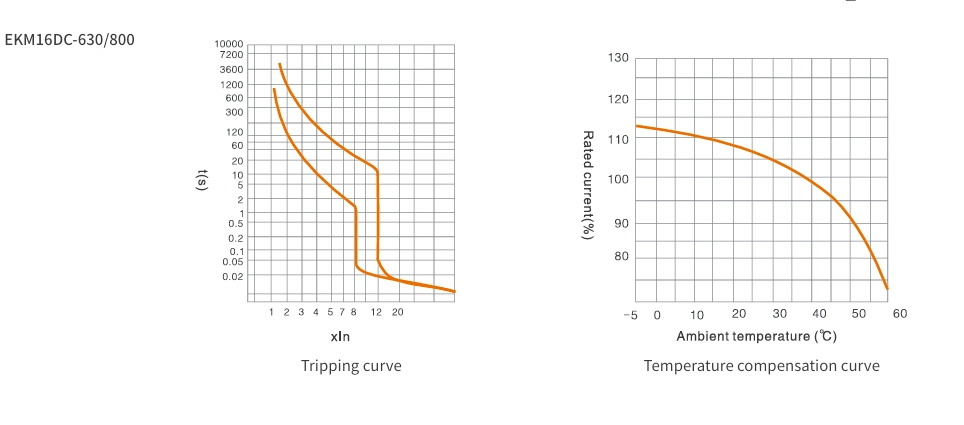
EKM16DC-630 1.0In 1.0In 1.0In 0.92In 0.90In 0.89In 0.83In
EKM16DC-800 1.0In 1.0In 1.0In 0.92In 0.89In 0.85In 0.80In

Derating Coefficient of Technical Parameters Based On Altitude

Altitude (M) 2000 2500 3000 3500 4000 4500 5000
Max operating current coeff. 1 1 0.98In 0.95In 0.93In 0.91In 0.89In
Max operating voltage (V) Ue Ue Ue Ue Ue Ue Ue
Power frequency withstand (V) U U U U U U U

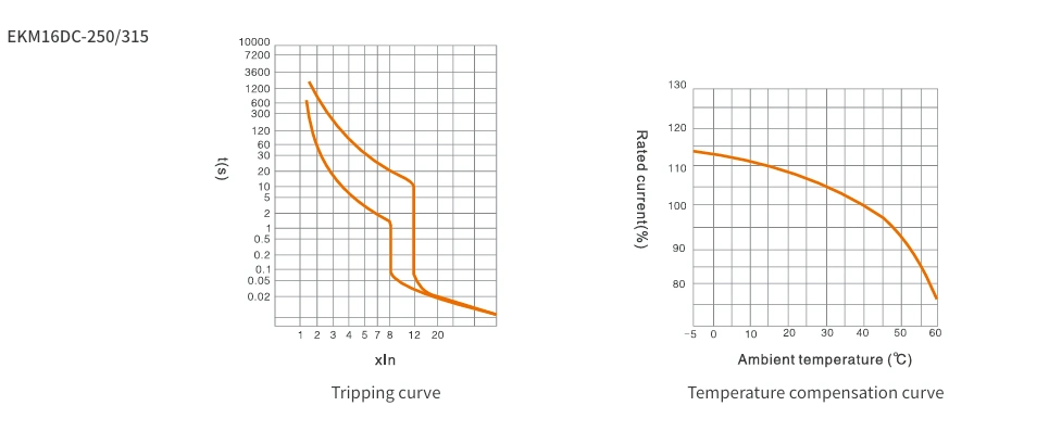
Tripping Characteristic Curve

EKM16DC-250/315 Tripping Characteristic Curve


EKM16DC-400 Tripping Characteristic Curve


EKM16DC-630/800 Tripping Characteristic Curve

Dimensions and Wiring of the Molded Case Circuit Breaker

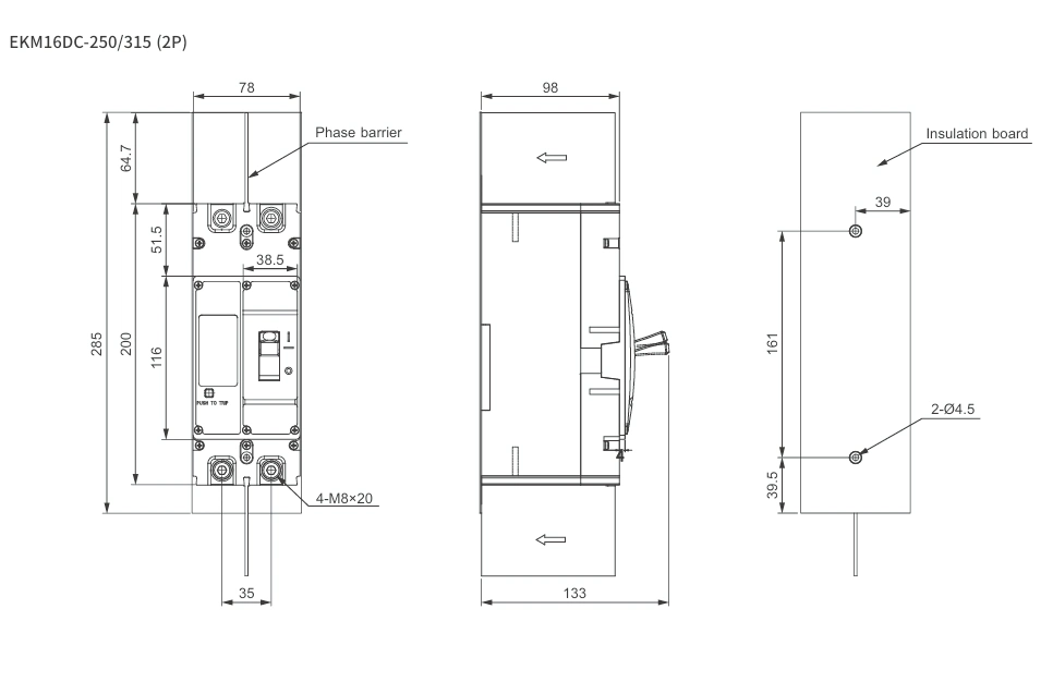
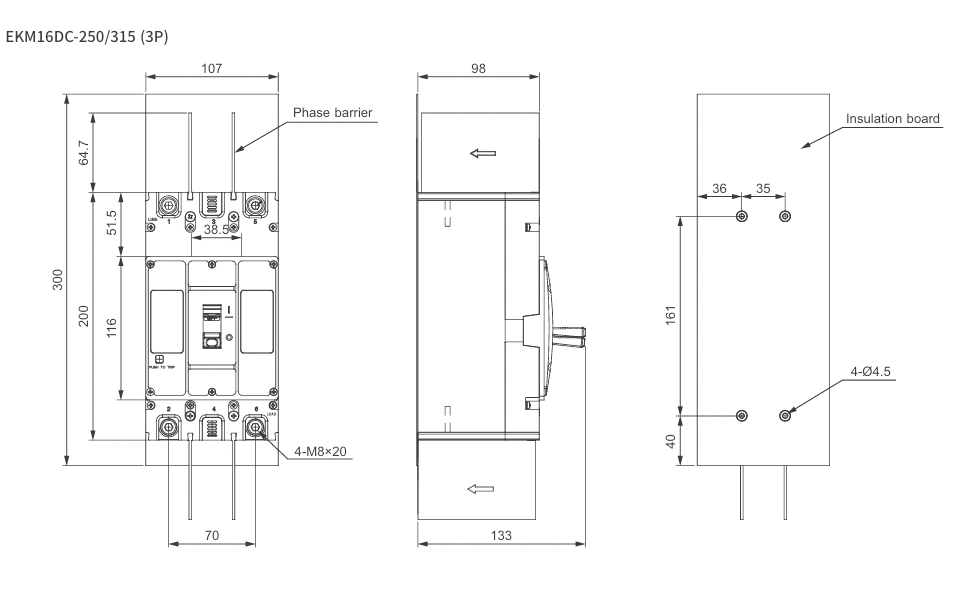
Verify the exact modular footprints and heavy-duty terminal clearance below to guarantee perfect panel fitment for this Molded Case Circuit Breaker.

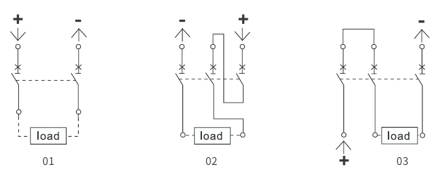
Wiring Diagram

Wiring Diagram 01 02 03

Overall Dimensions (mm)

EKM16DC-250/315 (2P) Overall Dimensions


EKM16DC-250/315 (3P) Overall Dimensions


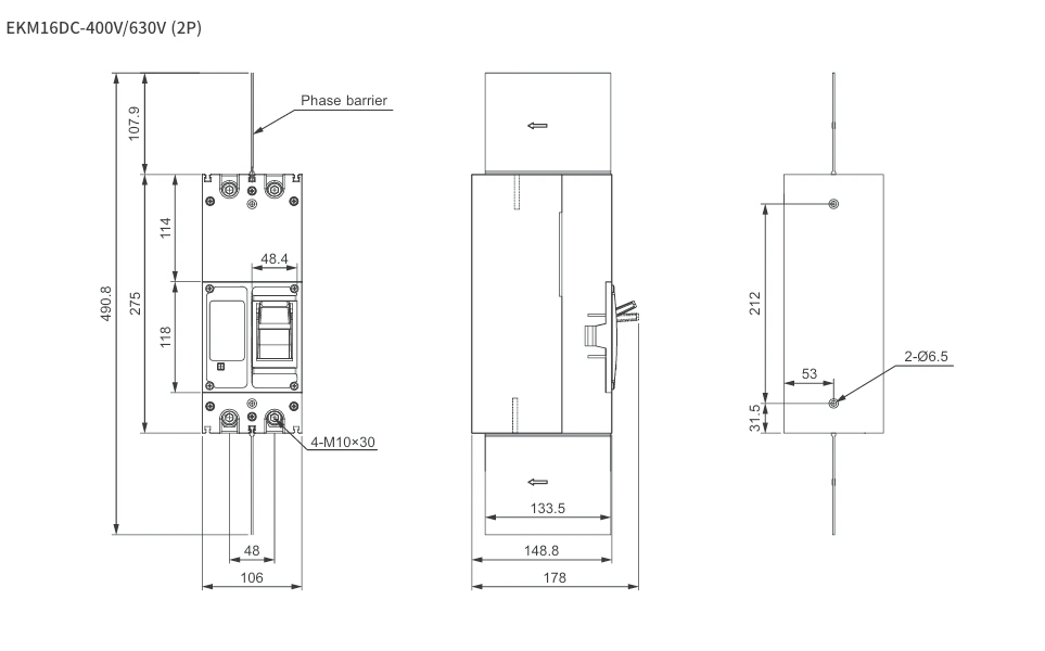
EKM16DC-400V/630V (2P) Overall Dimensions


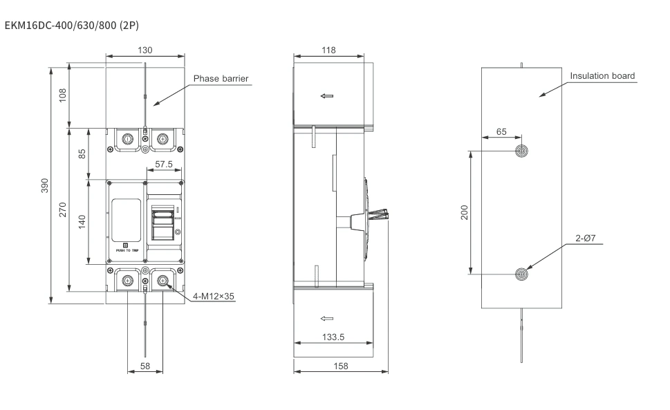
EKM16DC-400/630/800 (2P) Overall Dimensions


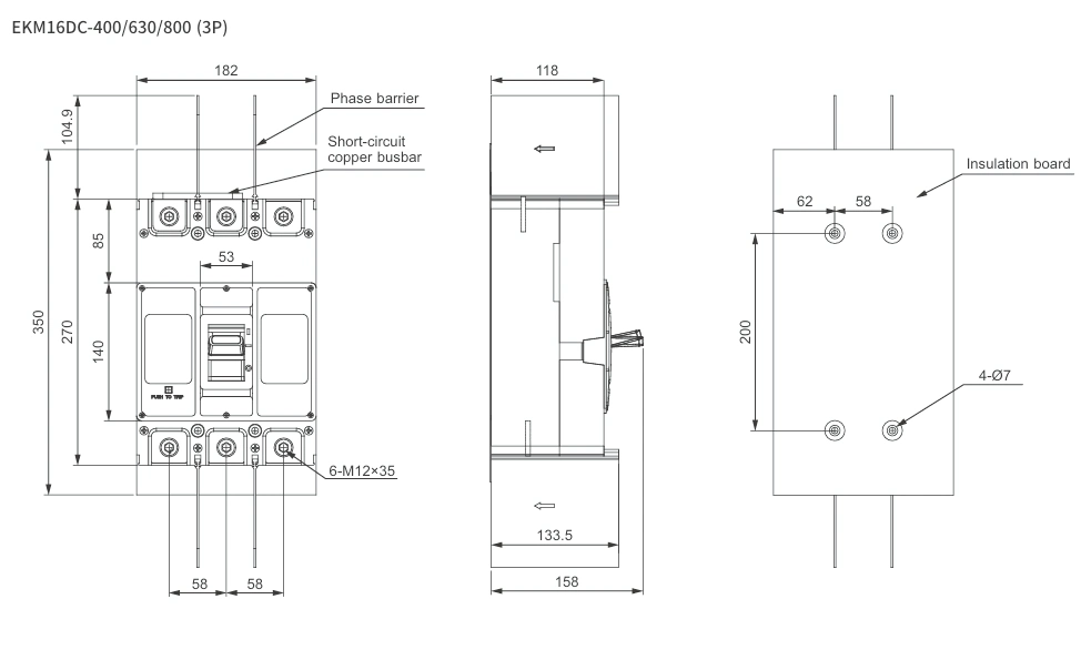
EKM16DC-400/630/800 (3P) Overall Dimensions

Request a Quote

Get pricing for EKM16DC_MCCB

Complete the form and our sales engineers will reply with pricing, lead time and certification documents.

Chat on WhatsApp