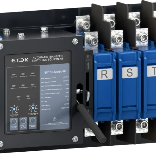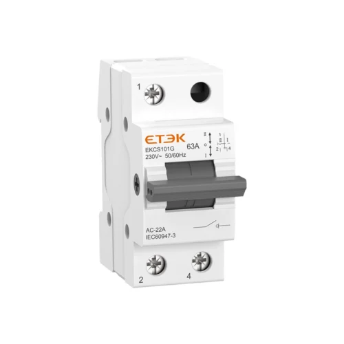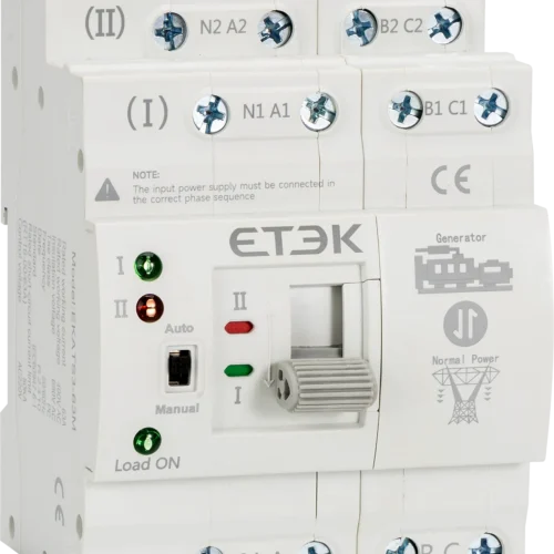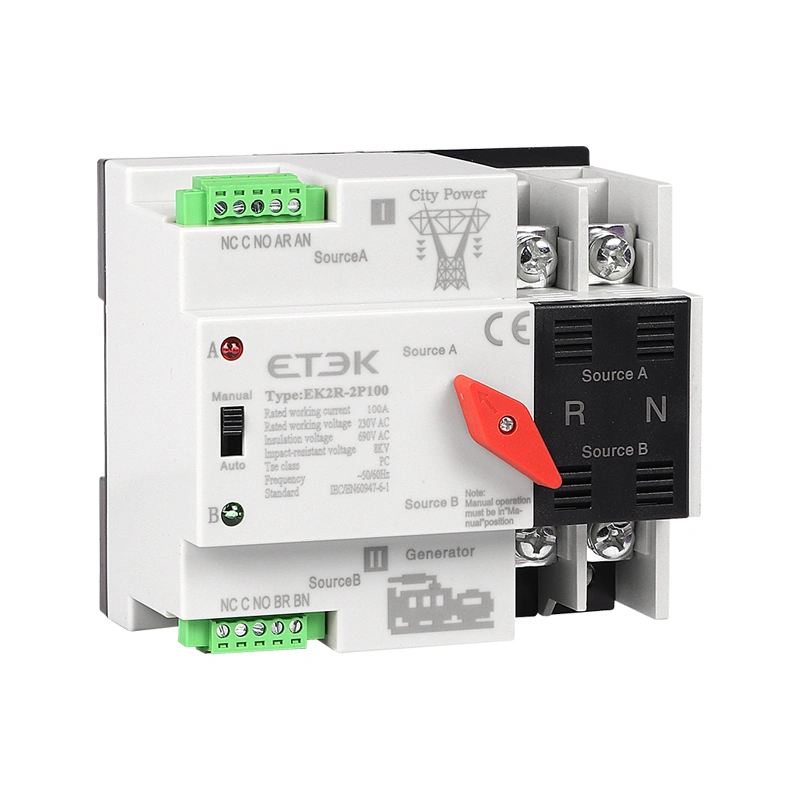
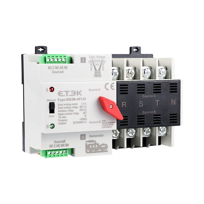
Solar Automatic Transfer Switch AC 125A 400V 50kA Protection

Securing critical AC power distribution, this resilient Solar Automatic Transfer Switch executes immediate source shifting in under 50 milliseconds. Designed for continuous commercial operations, this automatic transfer switch subcategory component manages up to 125A loads to guarantee seamless integration between PV inverters and the municipal grid.

Request a Quote

Pricing is quoted per order — tell us your quantity and destination and our sales team will respond with a full offer.

ModelEK2R
AvailabilityIn stock
  • CE & TUV certified
  • Worldwide shipping
  • OEM & ODM support

Product Features of the Solar Automatic Transfer Switch

Engineered with a robust PC-Class change-over mechanism, this Solar Automatic Transfer Switch guarantees safe electrical isolation during emergency AC power shifts.

  • High-Speed Conversion: Executes automatic switching within 50 milliseconds, minimizing downtime for sensitive 400V AC commercial loads.
  • Dual Power Configuration: Tailored for PV solar installations where Source A connects to the inverter’s AC output and Source B links directly to city power.
  • Robust Fault Withstand: Resists massive grid anomalies utilizing a 50kA rated conditional short-circuit current capacity and an 8kV impulse withstand voltage.
  • Broad Rating Compatibility: Supports versatile system sizing, functioning seamlessly as a heavy-duty ats 125 amp configuration or scaling down to 16A.

Type Designation Guide

EK2R Configuration Structure
Code Meaning
EK Company Code (ETEK)
2R 2R series automatic transfer switch
Pole 2P, 3P, 4P
Rated Current 16, 20, 25, 32, 40, 50, 63, 80, 100, 125A
Type Blank: Normal type; PV: Solar type

Front Panel Components

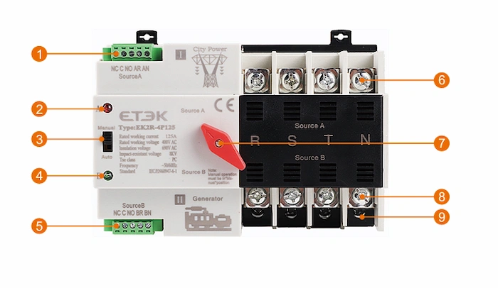
To facilitate safe operation and rapid maintenance, the physical architecture of the EK2R includes nine distinctly mapped functional components:
Solar Automatic Transfer Switch

  1. Main Power Composite Block: Secure terminal assembly for primary AC control connections.
  2. Main Power Indicator: LED confirming main grid power availability.
  3. Selector Switch: Toggle for manual/automatic operation modes.
  4. Standby Power Indicator: Visual alert verifying secondary backup source readiness.
  5. Standby Composite Block: Terminals for backup control wiring.
  6. Primary Input Terminals: Main AC power input routing.
  7. Manual Rotary Switch: Physical override handle for direct transfer.
  8. Secondary Input Terminals: Standby emergency power input routing.
  9. Load Terminals: Power output routing directly to facility loads.
Field Applications for the Solar Automatic Transfer Switch

Integrating the EK2R series prevents catastrophic power loss across AC infrastructures relying on a dependable Solar Automatic Transfer Switch.

Applications & Use Cases

  • Photovoltaic Systems: Integrates the AC output from solar inverters with the municipal grid to form a seamless automatic transfer switch 125a safety node.
  • Generator Integration: Functions as a highly responsive 125a ats switch to trigger and transition to generator backup during primary grid failures.
  • Emergency Power Distribution: Secures uninterrupted supply for critical facilities serving as a robust 125 amp automatic transfer switch where power failure is strictly prohibited.

Easy Installation Instructions (System Layout)

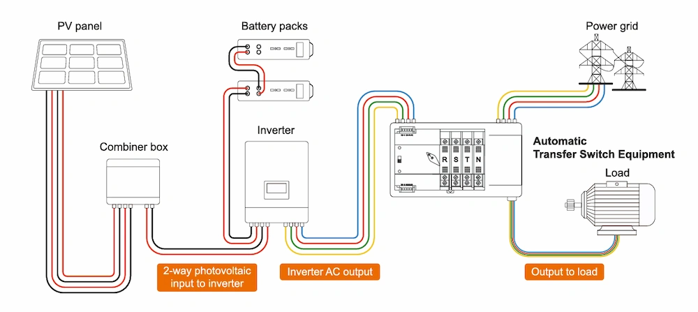
The PV-optimized wiring architecture follows a strict energy routing sequence to maximize renewable utilization before grid intervention.

Solar Automatic Transfer Switch Easy Installation Instructions

  • Routing Flow: Solar arrays feed the Combiner Box, moving into the Inverter alongside Battery Packs. The Inverter’s AC output connects to Source A on the ATS, while the Power Grid connects to Source B. The ATS then delivers stable power directly to the load.

Technical Specifications with the Solar Automatic Transfer Switch

Evaluate the precise alternating current parameters below to align this ats 125a component perfectly with your IEC60947-6-1 distribution requirements.

Main Electrical Data

Electrical Parameters
No. of poles 2P / 3P / 4P
Rated voltage (Ue) 110V/220V (2P) | 220V/400V (3P, 4P)
Rated current (Ie) 16, 20, 25, 32, 40, 50, 63, 80, 100, 125A
Insulation voltage (Ui) AC 690V
Frequency 50/60Hz
Usage category AC-33iB
Rated conditional short-circuit current (Iq) 50kA (SCPD fuse: RT16-00-63A)
Rated impulse withstand voltage 8kV
TSE class PC class (loaded switching without generating short-circuit current)

Switching Times & Control Circuit

Transfer Operations
Contact / Operating / Return / Off time < 50ms
Control circuit (Us) AC220V / AC110V, 50Hz (Normal working condition: 85%-110%Us)
Auxiliary circuit AC110V / AC220V, 50/60Hz
Temperature range -5°C to +40°C (Average ≤ 35°C in 24 hours)
Mechanical / Electrical life ≥ 5000 times / ≥ 2000 times

Panel Description & Operating Modes

Proper identification of indicator outputs and signal mappings is critical for maintaining controller integrity across different deployment modes.

Panel Description Solar Automatic Transfer Switch

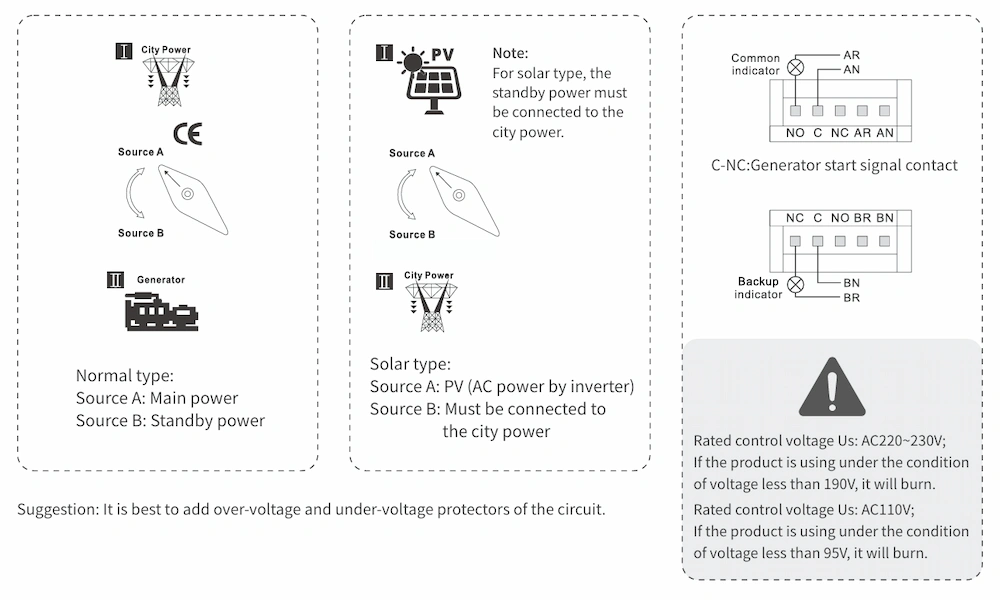
  • Normal Type vs. Solar Type: In Normal mode, Source A is the Main grid and B is Standby. In Solar Type, Source A must be the PV Inverter AC output, and Source B must be connected to the city power.
  • Signal Contacts: C-NC acts as the Generator start signal contact.
  • Voltage Warning: Supplying less than 190V to a 220V-230V rated control circuit, or less than 95V to a 110V circuit, will critically burn out the controller.

Dimensions and Wiring of the Solar Automatic Transfer Switch

Verify exact enclosure clearances and control wiring layouts associated with this Solar Automatic Transfer Switch for safe panel mounting.

Wiring Diagram of Controller

Executing proper stepped wiring guarantees arc-free load connections and protects internal logic boards.

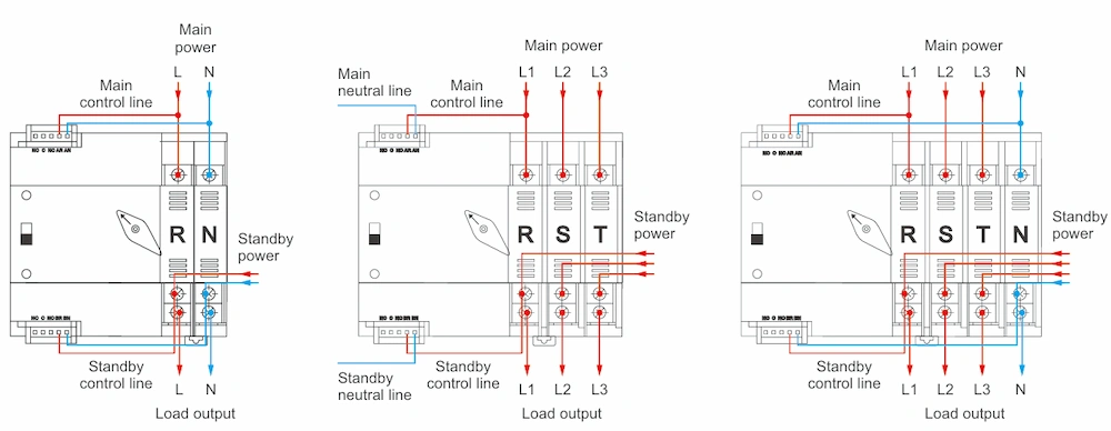
Wiring Diagram of Controller Solar Automatic Transfer Switch

  • Control Lines: Must tap the zero and fire lines from the main incoming feed to connect AR (live) / AN (neutral), and symmetrically for the standby feed to BR / BN.
  • Isolation Board: Remove the isolation board prior to wiring, connect the load in a stepped configuration (standby side lower end), and reinstall the board afterward.

Dimensional Data (mm)

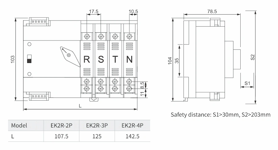
To maintain optimal thermal dissipation, respect mechanical safety distances of S1 > 30mm and S2 > 203mm around the switchgear housing.

Model Length (L) Height Depth
EK2R-2P 107.5 mm 104.0 mm 78.5 mm
EK2R-3P 125.0 mm 104.0 mm 78.5 mm
EK2R-4P 142.5 mm 104.0 mm 78.5 mm

Solar Automatic Transfer Switch Dimensional

Request a Quote

Get pricing for EK2R

Complete the form and our sales engineers will reply with pricing, lead time and certification documents.

Chat on WhatsApp